Thursday, January 19, 2006

Problem for X-ray Anode

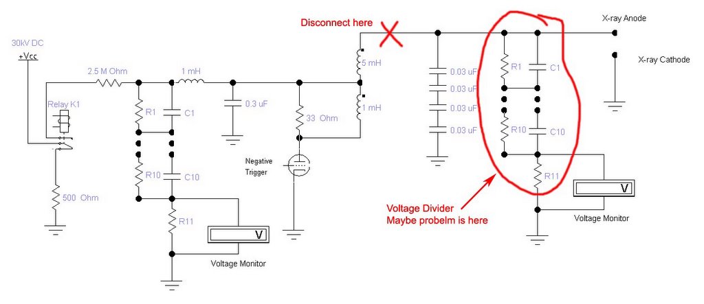
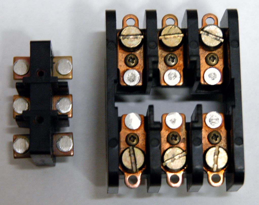
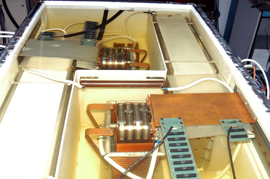
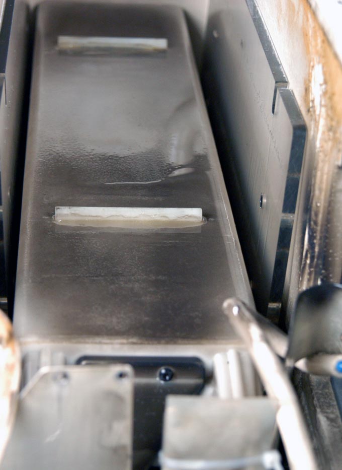
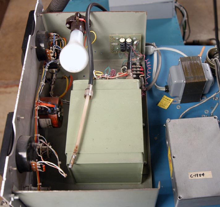
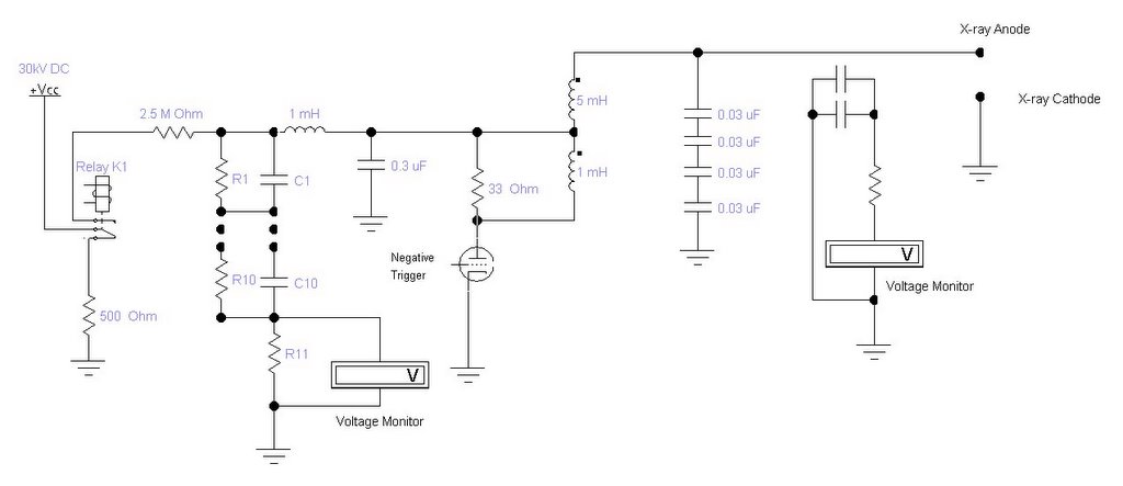
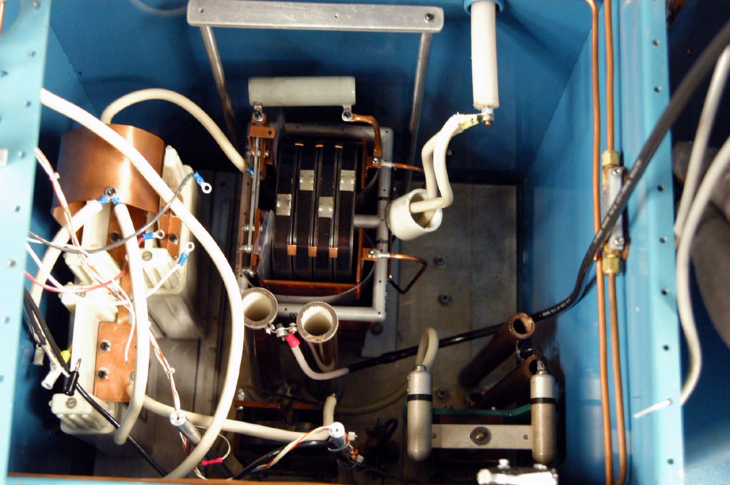
I opened the X-ray anode 4 caps oil tank, and took the X-ray Anode trigger signal sampling circiut board(shown as right picture). This voltage monitor plate is different from what I imaged. This plate is placed near the high voltage cable, the cable radiation will induce a small voltage through capacitors. This induced signal is used to measure the x-ray anode pulse. The circuit drawing is revised correspondingly, please check this link. As a result, we don't worry about the voltage divider as we thought yesterday.

I pulled out the 4 caps and checked them separately, we did not find anything wrong. Then Mike suggested to measure the high voltage cable, so we disconnected the cable from the x-ray anode bar and applied 10 kV to the cable. The measured current was less than 0.1 mA, which means the cable is good. Up to now, we only left one item was not detected - X-ray anode bar. Thus we directly connected the anode bar without 4 caps. The measured current increased up to 1 mA as we slowly tuned the high voltage to 10 kV. We concluded that there must be a fixed resistance between anode bar and ground, the value was estimated by ~10M Ohms. As we kept increasing voltage to 20 kV, the current measured up to 1.5 mA, then droped a little bit. The current became unstable, swung between 1.2 mA and 1.5 mA. There may be two reasons to cause this phenomenon: 1) the flashover was occured on the surface of conical epoxy bushing; 2) discharging between aonde pipe and cathode bar because of the anode pipe bending .

Wednesday, January 18, 2006

H.V. for thyratrons OK! Check X-ray Anode trigger independently

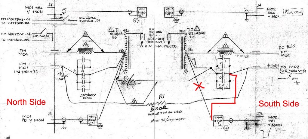
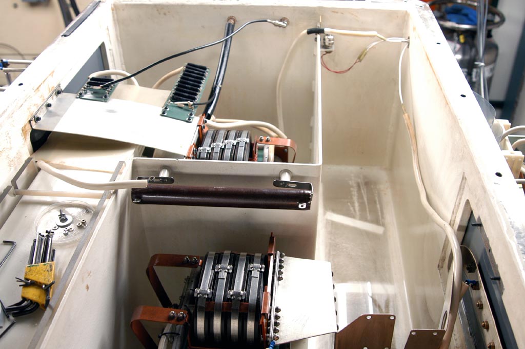
I pumped the oil from top tank and checked connects inside the oil tank carefully. I found where the problem was finally. Then main point is the voltage monitor connection. This voltage divider should be connected after the charging capacitors(black line), but it was put before them(red line, wrong connect). It's impossible to charger the caps, the voltage were drained down through resistors before charging the caps. I remembered that I installed the north side by myself after cleaning, and the south side was connected by other guys. I have not checked the wire connection after installing whole system. This gave me a lesson seriously, which is that I must check the circuit carefully anywhere and anyhow.

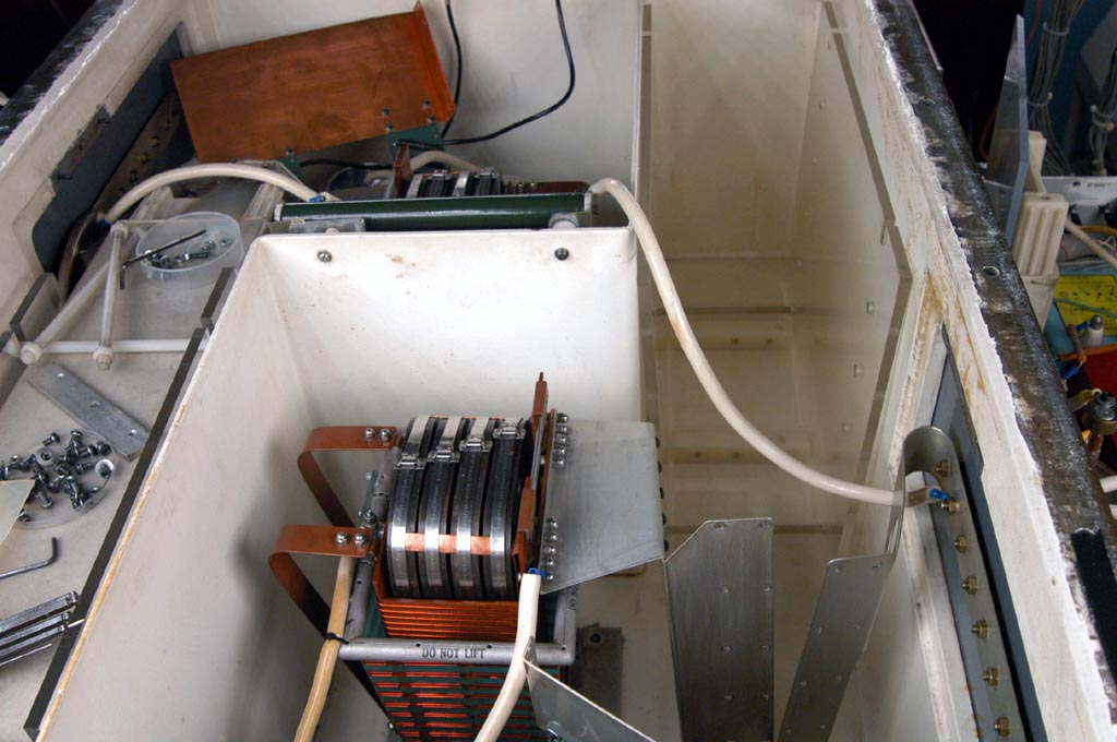
The system ran well in the afternoon except the x-ray anode randomly triggered. Mike suggested measuring the anode high voltage power supply independently. Firstly we only gave the power to 30kV HV power supply, in this case we don't worry about the low level trigger. When I increased the voltage slowly to 10kV, the current meter showed about 1~2 mA steadily. From the circuit drawing, the current should keep lower than 0.5 mA. We guessed the resistors might have problem. Then we disconnected the cable between transformer and 4 caps (shown as in the picture) and checked the front end circuit separately. This time we increased the voltage gradually to 30 kV, the current always was kept around 0.2 mA. Now it's pretty sure the breakdown was came from either caps, x-ray anode voltage divider or x-ray anode bar. The 4 caps are brand new, and just were replaced last month. They can be excluded. We will check the voltage monitor for x-ray anode tomorrow.

I also changed the O-ring for oil circulation system. I found the O-ring became crispy so that caused the oil leak from the seal slit. The O-ring model is 261, Kevin helped me to find it from the work shop.

Drawing list

I sent the 24 pieces of schematics not including mechanical drawing to Randy for scanning. The drawing list is shown below.

  1. C1781 UTILITY REQUIRMENT LAYOUT
  2. C1820 X-RAY ANODE H.V.P.S XFMR TANK M05-B
  3. C1821 X-RAY ANODE H.V. CONTROL M05-A SCHEMATIC
  4. C1823 X-RAY CATHODE TRIGGER M11 SCHEMATIC
  5. C1824 TRIGGER P.C. BOARD
  6. D1830 SYSTEM CONTROL R01 SCHEMATIC
  7. C2153 PULSE MODULATOR VOLTAGE CONTROL BOX
  8. C2154 MK2 PFN VOLTAGE TONTROL P.C.B
  9. C2155 P.M. VOLT CONTROL TIMING P.C.B
  10. C2156 LOW VOLTAGE POWER SUPPLY M04 SCHEMATIC
  11. C2269 TEMPERATURE CONTROL R02 SCHEMATIC
  12. C2270 H.V. CONTROL R03 SCHEMATIC
  13. C2271 H.V. CONTROL P.C. BOARD
  14. C2272 GAS PROCESSOR CONTROL
  15. D2293 PULSE MODULATOR #1 M01 SCHEMATIC
  16. D2294 PULSE MODULATOR #2 M02 SCHEMATIC
  17. C2302 ANODE H.V. CONTROL P.C. BOARD
  18. C2304 PULSE TRANSFORMER M06 SCHEMATIC
  19. D2314 INTERCONNECT BOX M00 SCHEMATIC
  20. D2316 OIL SYSTEM INTERCONNECT BOX M08 SCHEMATIC
  21. C2377 H.V. CONTROL P.C. BOARD
  22. E2329 INTERWIRING DIAGRAM
  23. B2596 FIL VOLTAGE LOW INTERLOCK BOARD SCHEMATIC
  24. A2690 PERVENT TRIGGER BOX SCHEMATIC

Tuesday, January 17, 2006

HV Power Supply

The resistance of the big transformer primary and secondary were measured, the value of the primary was zero, and the secondary 2k Ohm. Keith said that values are reasonable. I also checked the H.V. after disconnecting the cable to the thyratrons. The voltage obviously could be monitored. It means the HV power supply works very well. It must be somewhere not good after the HV power supply. I pumped the top oil tank to check the caps, chokes and transformers again. Because the wired phenomenon of no HV monitor was happened just after we cleaned the top tank oil and installed the caps last month.

Changed the dry compressed air cylinder for spark gap switch. Changed some damaged resistors.

Friday, January 13, 2006

High Voltage Board

We bypassed the SCR CD430440 to measure the transformer primary input voltage, the value was ~200V as we turn on the H.V. switch. But the HV meter was 0 V. Mike guessed the rectifiers may be broken, so we removed them for detecting. We applied a +1kV DC and -20 V DC to the rectifier one by one, we did not any one was damaged. We also checked the connect of 10 k Ohm resistors, and have not fond anything wrong. The resistor for current monitor also measured, the value is 70 Ohm. Till now we leave transform and voltage divider not be checked.

Thursday, January 12, 2006

Pulse Modulator H. V. Power Supply

I checked the X-ray Anode Control Box (MO5A) this morning. Mike suggested me to monitor the trigger signal of Anode H.V. Control PC Board (circuit drawing C-2302). We found the optically couple isolator phototransistor 6N136 was broken. After replaced the damaged chip, the X-ray anode can be triggered.


However, the 30 kV for thyratrons still could not be applied. Mike and I checked the low level circuit and did not find anything wrong. Then we firstly measured the voltage cross relay K4, it's ~205 V as the relay switched on. We were afraid that the SCR could not be controlled, so we monitored the voltage crossed SCR, it's ~200 V when the control panel H.V. switch was off. The value became to 0 V as the H.V. switch was on. It means the SCR and control system working correctly, but the H.V. meter show the voltage was 0 V. We will check transformer and rectifiers tomorrow.

Wednesday, January 11, 2006

No voltage supplied for Anode Hiptronics power supply

The repaired Lecroy oscilloscope was sent back this morning, we can use it to record the waveforms from now.

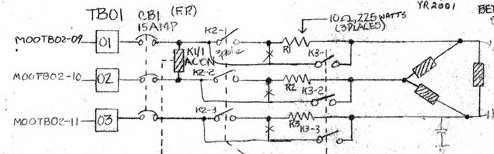
I received the new relays this afternoon, the circuit breaker was still kicked off after settling down them. Mike suggested to check the voltage phases. I found that I connected K3-1 and K3-3 incorrectly. The filament voltage became normal(~5.4 V DC, each side 2.7 V) after switching these two connectors. Then I tried to test the whole system, but this time there was no voltage spplied to Hiptronics High Voltage Power Supply. I measured the voltages on the MO5B board, the TB01-01 and TB01-03 both are zero, they are connected to MO5ATB03-01 and MO5ATB02-09 respectively(circuit drawing shown right). So I will check MO5A tomorrow.

News: Laser-driven proton

Recently, it has been observed that intense, collimated beams of multi-MeV protons were generated in the forward direction by intense short-pulse lasers irradiating thin solid foils at the Laboratoire pour l’Utilisation des Lasers Intenses(LULI) of CNRS. This discovery of an intense (~10^11 protons/shot with a maximum energy of ~25 MeV), pulsed (duration less than 1 ps), laminar source of protons has opened new and fascinating perspectives.

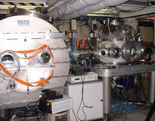
he production of such high current protons and ions beams have been made possible by short-pulse, ultra-high intensity lasers (laser pulse duration less than 1 ps, power density more than 10^18 W/cm^2 um^2) such as the one at LULI(see photo on the right showing the compressor and target chamber). There are several mechanisms that can lead to laser-acceleration of protons in the forward direction. In experiments performed at LULI, it has been unambiguously demonstrated that rear-surface acceleration is the predominant mechanism to get protons of high energy. In this mechanism, relativistic electrons generated at the laser-irradiated interface by the intense laser and propagated through the target form on the non-irradiated rear-surface of the target a dense electron plasma sheath. Its strong (~TV/m) electric field can ionize atoms and rapidly accelerates ions normal to the initially unperturbed surface. The accelerated protons stem either from hydrogen-containing contaminants (e.g. water vapour) that are present on all target surfaces or from prepared layers.

J. Fuchs, et al,Laser-driven proton scaling laws and new paths towards energy increase, Nature Physics 2, 48-54 (2006).
Laser Interaction group of LULI and Ecole polytechnique

Tuesday, January 10, 2006

Cleaned the Relays

The ordered relays have not been received until this afternoon, so I tried to clean the old relays by myself. Because the pin surfaces were burned very much, I have to file them so that pin thickness became less than before. In order to check the refurbished relays, I put them back to test, however the circuit breaker shut down once again. Then I disconnected the transformer output to purify the test condition, I found the relay K2 was close in the beginning. After 1 minutes time delay the relay K3 should be closed, but the circuit breaker was shut down while K3 was reacting. I estimated the primary problem is K3 caused circuit breakdown. The refinished relay K3 may not be used again.

Monday, January 09, 2006

History of Prometheus

I removed relays K2 and K3 from the MO4 circuit board. They looked very dirty, I disassmbled one and found some copper pins were burn into black. I am not sure these relays can be used again after cleaning the dirty pins, I think it's better to use new relays. Unfortunately I have not reveived them from Newark.

Randy wrote down a report about Prometheus, the followed is the part about its history. Thanks Randy!
********************
History of Prometheus (by Randy Carlson)

Prometheus is one of two identical amplifiers delivered to both Los Alamos and UIC in the spring of 1988 by Beta Development Corporation under Gary Loda (now deceased). The device consists of two main discharge cavities (10cm x 10cm x 2m long) that share a common x-ray pre-ionizer that operates at 150 kV. Originally, each main discharge electrode was driven by a two-stage saturable core compressor with the main voltage step-up achieved by a 6.33:1 Stangenes autotransformer. The prime energy store is at 25 - 30 kV and switched to each discharge side (called North and South) by a North and South bank of six Thyratrons. This design architecture was chosen by the manufacturer as a way to achieve ~ 1 Hz or more repetition rate operation and results in a final fast rising voltage pulse of 150 ? 180 kV on the main discharge anodes. At Los Alamos and UIC the discharge cavities were utilized in a folded series configuration except that Los Alamos used a XeCl based gas mixture at 3 atm and UIC uses a KrF based gas mixture at about 1.6 to 1.7 atm.

Shortly after installation, two main changes were made to the x-ray pre-ionizer: (1) the smooth conical epoxy bushing that had evidence of flashover was machined with grooves, and (2) x-ray masks were utilized in an attempt to control the area for main energy disposition in the laser cavity. The first of these changes is present in the UIC amplifier but as for the second change. Another area of change was the replacement of both stages of saturable cores and one set (an array of 80 ceramic capacitor stacks) with two Maxwell Rail Gaps. Both sides of the UIC amplifier have the Maxwell rail gaps installed and other than annual maintenance are working in a flawless fashion. The Los Alamos system was salvaged in the mid-1990s.

Friday, January 06, 2006

Randy visited lab

Randy visited our lab today, he gave me many suggestions about high voltage pulsed power. I told him how the system run, what's main problem we have and gave him the documents and circuit drawings.

I wanted to show Randy the X-ray gun triggering, however the MO4 circuit breaker was shut down just after several minutes. I guessed the relay K2 or K3 was not good, because I have not changed them yet. I hope I can receive the parts next Monday.

Thursday, January 05, 2006

Wavelength Measurement of Coherent Innova 90

We ran the old Coherent INNOVA 90 Ar ion laser for new interferometer measurement in the new target chamber. We are not sure the output wavelength, so I used the CVI spectrometer to measure it.

Wavelength selection is dependent on the type of rear mirror holder. The INNOVA 90 can be operated with either of two types of rear mirror holders: a multiline mirror holder which produces operation in the all lines, or the Model 934 Wavelength Selector which produces operation in the single line.

For multiline operation, the multiline mirror holder should be used. When switching from single line operation to multiline operation, peak the output at 488.0 nm for argon system. The wavelength calibratiors located on the control panel should be set to read 488 nm for multiline argon operation.

Wednesday, January 04, 2006

Relay K3

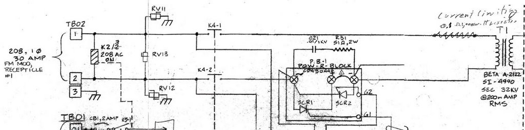
I ran the system after tightening the charging resistor connector, unfortunately the high voltage still could not apply to the caps. The circuit breaker (CB1 as shown in the picture) was switched off after several minutes. Mike helped me to check the circuit drawing, we guessed the problem may be from the relays K2 and K3, so I measured the voltages crossing them. The relay K2 worked well. But the voltage cross resistor R1 was ~30V, it means the K3-1 connect is very bad.

I removed the relay K3, found the connect pin was very dirty and the connect surface was so rough. The shape of one pin was changed, so that it could not attached the wire connector well. The relay model is P25P42A22P1-120, the manufactory is Potter & Brumfield. I ordered it from Newark online.

Tuesday, January 03, 2006

Checked the system

I ran the Prometheus this afternoon, however the x-ray gun still was unstable. The new problem was the high voltage could not be applied to the rail gap. The filament switch was turn off after running several mintues, then I found the fuse was broken. I measured the Primary voltages, the north bank looked well, but there was no signal from south side.

I changed the fuse and the one 27 Ohm resistor for Thyratron at South bank.

Friday, December 23, 2005

Wednesday, December 21, 2005

Captive nuts

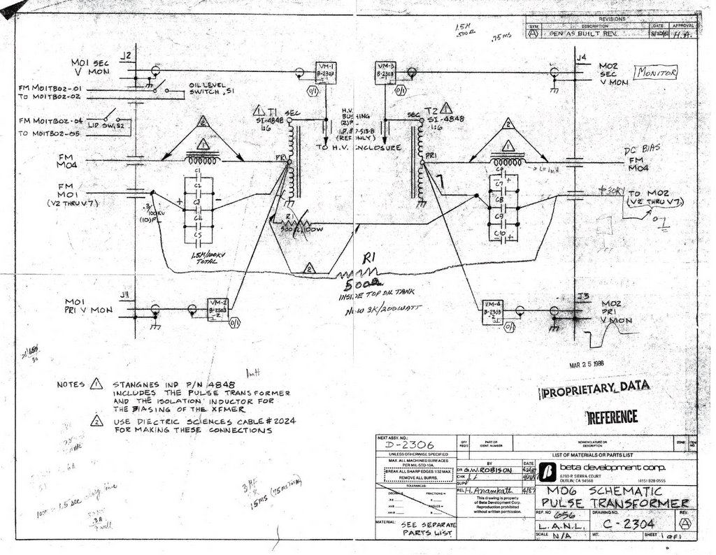
I ordered captive nuts from McMaster-Carr, the part number is 95185A191: Zinc-Plated Steel Clinch Captive Nut 10-32 Screw Size, .091" Minimum Panel Thickness, the style: Hex Head Clinch Style. However they delieved wrong captive nuts.The above is the MO6 pulse tranformer schematic drawing, Keith and Bill replaced the 500 Ohm 100W resistor with 3k Ohm 200W resistor before. Keith said it's not big deal to use a 1.5k Ohm resistor.

Tuesday, December 20, 2005

Moving the caps from South Bank

We moved the capacitors from the South Bank, I found this side was clearer than North Bank, since we cleaned south last year. Mike checked the power supply for Anode Thyratron filament, he could not find any problem. The caps and choke are all right.

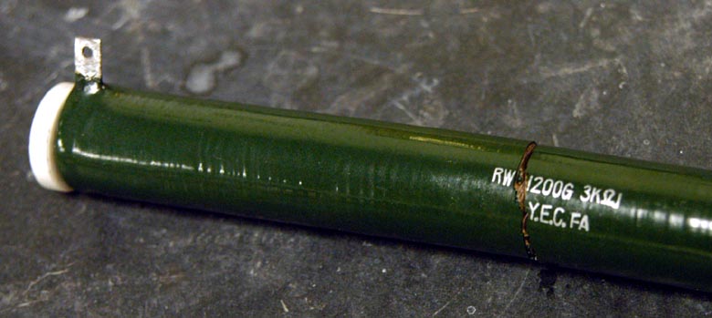
The other trouble is the resistor connecting South Bank caps and North Bank caps, it's broken when I tried to disconnect the cable. This resistor is 3k Ohm, 200 Watts, I did not find the same resistor from electrical shop. They only have 1.5k Ohm, 225 W resistors. I am not sure if I can replace 3k Ohm with 1.5k Ohm. From the circuit drawing, I found the original resistor was 500 Ohm.

Monday, December 19, 2005

Cleaning the top oil tank for North Bank

I asked Mike to check the X-ray anode thyratron filament power supply, because Keith guessed the capacitors or chokes for this power supply may not be well.
I pumped oil out from the top oil tank and found caps surface were very dirty. I took 5 pieces of capacitor for cleaning, and put them for drying over night. I will put them back tomorrow morning, and clean the south bank caps too.

Friday, December 16, 2005

Cleaning the 0.3 uF caps

This morning Mike helped me to measure three capacitors. We used Hipotronics 30kV 5mA power supply, connected 10k Ohm resistor and measured capacitor. When the voltage was slowly increased to 30kV, the current was around less than 0.1mA. It means the caps were good. We only heard a little click from one cap, it may be caused by the dirty surface. So I cleaned all the capacitors, then installed after drying.

I tested the system again in the afternoon, however I could hear the click sound from the oil tank, the voltage could not reach 150 kV anymore. I could not receive any signal from X-ray meter. I heard crack noise from the top oil tank at the same time. When I measured the voltage of the south bank and north bank, I found the north bank voltage was fine, but the south bank voltage was missed one to two per 10 shots. I am wondering if the rail gap trigger effects the x-ray gun? I plan to clean the top oil tank next Monday.

Wednesday, December 14, 2005

High Voltage Cable Connector

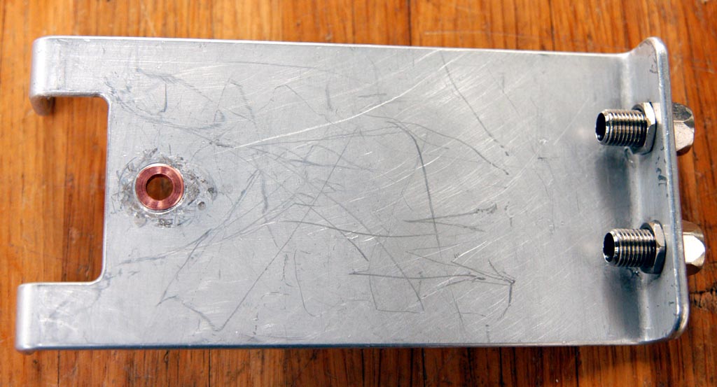
Kevin helped me refurnish the anode connect plate, which looks pretty good. He put a copper hole to replace the arcing hole.

I also cut the 150kV cable end and thread it. But it's very hard to put the cable back to the cap tank. Finally I put it into the tank, but it's silly not to fix it very well, there was oil leak from the connector.

Tuesday, December 13, 2005

Hipotronics Power Supply Output Cable

In the morning, I checked the HIPOTRONICS 30kV DC Power Supply. When this equipment was open, the voltage monitor showed 30 kV as I set the output to full scale. When I took out the output cable, I found the cable end was burned because of the arcing. I contacted Hipotronics company, they will charge us $190 for a 3 feet cable and it will take a week for delivery. Fortunately I found a similar cable in the cabinet, I cut it to fit the power supply. But it's weird that click sound still has been heard inside the oil tank, I did not find the key to make the x-ray anode trigger failed.

The only part I have not checked is the 150 kV cable connector with the capacitors, I already drained the cap oil tank. I will check the connector tomorrow.

Monday, December 12, 2005

X-ray Anode Trigger Unstable

We are lucky to find a 33 Ohm resistor from electrical shop. Then I pumped the oil out and installed the resistor, at the same time I checked the connectors of transformer, capacitors, choke, thyratron and charging resistors, and found some screws not tight. I tightened the loose screws then. But the x-ray anode could not be triggered normally. I still heard the clicks inside the oil tank and the high voltage could not reach 150 kV yet, which I described in my last email. An interesting phenomena is when I decreased the DC power supply voltage from 30 kV to 20-15 kV, I could not heard the clicks inside the oil tank. What caused this phenomena happened?

I also checked the anode control box, the input signal looks very good. I replaced the high voltage trigger for thyratron, the problem was still there. Till now, I checked every components except the 30 kV DC power supply and the Anode cable connector.

Friday, December 09, 2005

33 Ohm Resistor

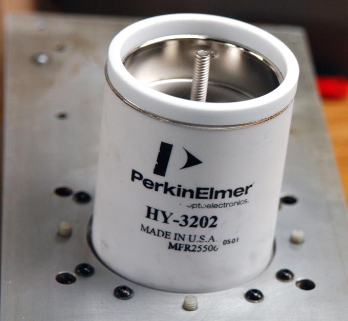
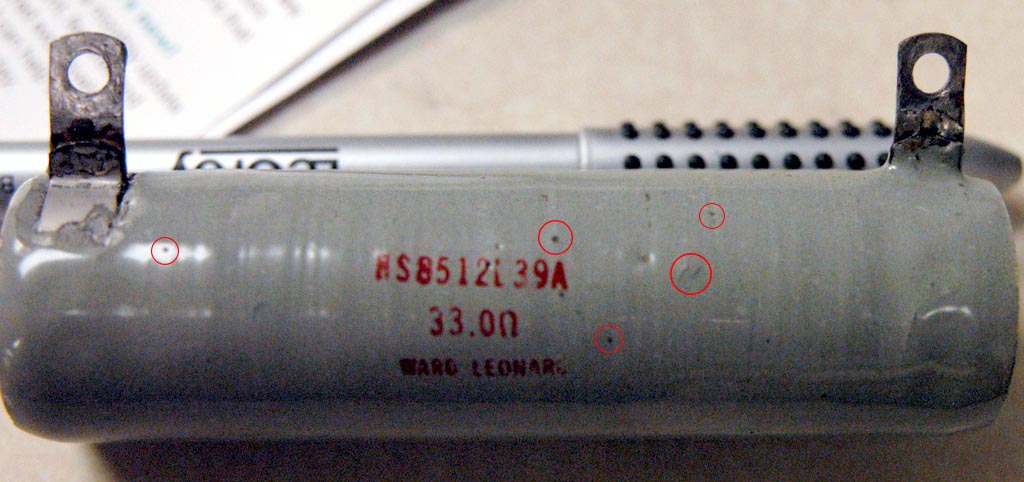
I put the PerkinElmer new thyratron HY-3202 into the x-ray anode control box this morning, but the anode trigger was not well yet. The x-ray anode high voltage was about 100 kV, I guessed there were some place breakdown in advanced. I checked the connectors in the oil tank, all of they looked very well. I pumped the slicon oil into the oil tank and tested the system again. I found there were arcings from the resistor which connected to the step up transformer. I took that resistor to check and found its surface not very good, there are many small holes. Please look at the picture, I marked the holes using the red circle. I think maybe the discharg was from the resistor surface and the ground.
Caution of HY3202 Installation instructions:
1. Keep tube envelope clean. Handle only by base, flange and anode stud. GLOVE SHOULD BE WORN.
2. Don't exert any force on pins, feedtrus or leads. Avoid any bending of pins. Don't carry tube by lead.
3. NEVER reduce reservoir voltage below 5.8 VAC. Tube can be destroyed.
The manufactor was Ward Leonard, model number is KS8512L39A, the resistence measured around 33 Ohm. I have not found this company from Internet. From Ohmite web site, I did not find the similar resistor. I phoned Bill, he said this resistor was used for prevent the high voltage kick back. He remembered that he had some resistors in the electric storge, I will ask Mike to find one next Monday. What if we could not find the resistor? Should I replace it with 40 Ohm or 50 Ohm resistor(I can find them from Ohmite company)? Could you tell me what power is this resistor?

Bill also reminded me that the dirty oil could cause the arcing, or the high voltage cable problems.

Thursday, December 08, 2005

X-ray Anode Trigger Failed

We received the 10k Ohm resistor this morning, then I installed it. In the afternoon I tried to passivate the system, it ran well until 4:30 pm. Then I heard clicks from the x-ray anode oil tank, the x-ray flux meter did not show any signal. I checked the reservoir and heater voltages for anode torturing, they were all fine. At the same time, the x-ray anode voltage monitor showed the high voltage could not reach 150 kV, it only went to 100 kV, then the voltage was dropped down to 50 kV (I heard the click from oil tank). This caused the x-ray gun running randomly, the system synchronization was failure. After checking the circuit drawing, I think there are three possible reasons to cause x-ray anode failure: 1) either SCR1 or SCR2 broken; 2) relay K1 control failed; 3) thyratron and its control unit not well. I plan to change the thyratron firstly tomorrow, then check SCR and relay K1.

The another bad news is the new Lecory oscilloscope is not working, so I could not save the waveforms.

Wednesday, December 07, 2005

Optical Path Alignment

I placed order of the 10k Ohm 225W resistor this morning, it should be received tomorrow morning. So I cannot run the Prometheus today. I checked the other part of the charging resistors, it looks good except some connectors. I fixed the connectors later. Mike helped me to find some resistors, unfortunately they were 100k Ohms.

In the afternoon, I aligned the optical path of the front end. The main point is the telescope alignment, it took me several hours to send the laser beam straightly into the Prometheus machine. I also found the first 2 mirrors not damaged, but the last one or two mirrors not good. I could see the shadows from them, it means the structure was broken inside.

Tuesday, December 06, 2005

Prometheus running

I changed the north bank thyratron CX1585 firstly. I replaced the damaged rectifier diodes ECG 5912 as soon as I received diodes from moyerelectronics. When everything was installed, I tried to run the system this afternoon, it's fantastic to hear the shooting sound again. I measured the CX1585 filament voltage, it's about 6.1 V DC. The x-ray gun cathode pulse could move forward to match the x-ray anode peak, the x-ray flux was measured about 2.5 mR/h.

The passivation was proceeded later, I filled a little bit fluorine gas into 1.2 bar He-filled chamber. In the beginning, the emission light was red, after running a couple of minutes, the light became white. Then I filled a little bit more fluorine gas, this time the red light kept almost one hour until I found a 10 k Ohm resistor was burning. This resistor was connected to the big transformer, it was very hot when the system running. Maybe because the temperature was too high, the connector was burned and the resistor became very crisp. It was broken as I took it out. Anyway I must put a new resistor tomorrow.

Monday, December 05, 2005

Big Rectifier Diodes

I checked the other rectifier diodes for Rail Gap thyratrons, I did not find any one was broken. As for the reason the ECG 5912 diodes were breakdown, I think the north bank thyratron CX1585 may be the key, when we ran the system I could see the arcing from the north bank. Maybe this disturbed the circuit and sent back a noise to the diode?

Today I ran the Spectra-Physics fs laser, it looks very well.

Saturday, December 03, 2005

Fuses Checked

===============================
Charlie and Song,

It is important to check the fuses in the box that we close and open to run the machine. These are in the top of Promethius and furnish a three phase power to all of Promethius. Their resistance should be measured across each fuse when the switch is open.
Regards
Keith
================================

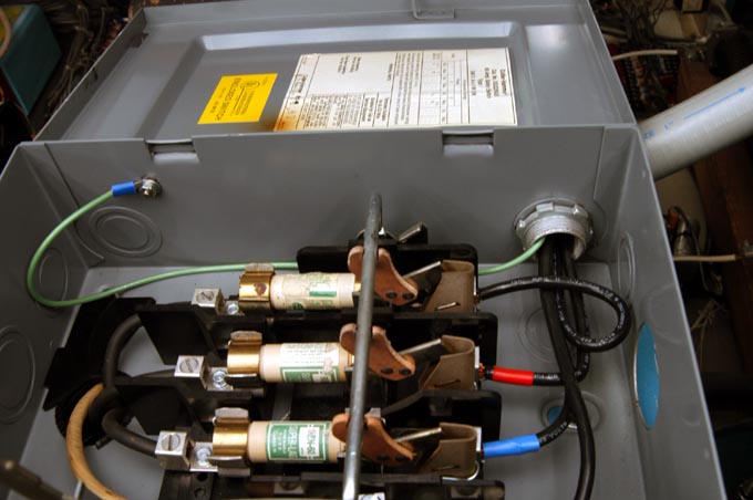
Along the Keith's email as above, I checked the fuses in the Prometheus power switch box, they are all fine. I also checked the 3 phase voltage, they are good, too. Please see the picture, make sure the switch box is corrected.

I pumped the gases out from the LLG-Twin Excimer front end, these gases has been kept inside the chamber for one month, I am afraid the F2 gas may corrade the O rings. I filled ~1 atm Helium gas inside the both tubes.

Friday, December 02, 2005

Silicon Power Rectifier Diode -- ECG5912

I checked the x-ray cathode trigger box this morning, and measured the output voltage of transformer. I did not find anything wrong, but the cathode pulses was not good. There must be something wrong, the only part was not checked is thyratron filament voltage.

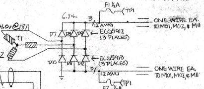
I measured that voltage, which was 2.7 V. It's lower than the normal value of 6.3 V. From the circuit drawing, this power was provided by M04 Low Power Supply. Please look at the attached picture, the 6.3 V DC is sent to M01, M02 and M11. M01 and M02 for rail gap, M11 for x-ray cathode. It may be two possible cases to decrease the low voltage, one is the thyratron of M01, M02 and M11 not working well, the other is the rectifier diode breakdown. I disconnected the diodes D7-D12 to check, and found D7 and D9 were totally breakdown, so the output voltage dropped to 2.7 V DC. This caused the thyratron CX1585 unstable, which finally effects the x-ray cathode pulses. I think the damaged diode is the main part to make the whole system failure. I did not find any replaced diodes in the lab, the electrical shop was closed when I found the problem. I will ask Mike to find the diodes ECG 5912 or order them next Monday. I hope the system would be run well after I replace the diodes.

Thursday, December 01, 2005

X-ray Cathode Power Supply

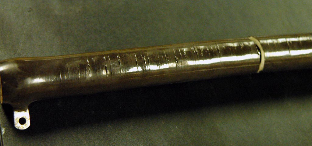
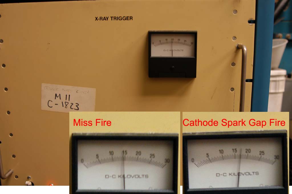
I ran the system this morning, the x-ray cathode pulse still was unstable. Sometimes the cathode spark gap missed fire. The high voltage monitor showed the voltage was 17 kV when the spark gap fired, but it was dropped down to 15 kV after several shots, then spark gap missed fires. Please looked at the picture named voltages.jpg. Mike suggested we should cut the voltage cable input ends, he guessed that damaged cables caused the voltage decrease because of the breakdown. So we cut both cable input and output ends. We really found there were some tracks on the cable surface, please check the pictures named "input ends.jpg" and "output ends.jpg".


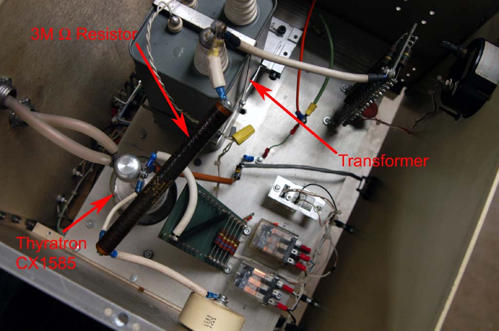
Unfortunately, the x-ray cathode spark gap still missed fires even I repaired the cable ends. We have not found the main point of the voltage decreasing yet. Mike guessed the 3M Ohm resistor does not work well, he asked me to check it tomorrow. But I think that the transformer may not work properly, since the voltage monitor is mearuing the transformer output. I want to measure the transformer output without connecting the thyratron firstly, make sure the voltage source is all right.

Wednesday, November 30, 2005

Cathode Power Supply Cable

I fixed the used spark gap and put it into the trigger generator this morning. In the afternoon, I tested the trigger generator, it worked very well. It's better to buy a new spark gap as a backup, I contacted Chip Yang from General Atomics, because they did not produce this part, he transferred my email to another company(Dave Drury at L-3 Titan PSD, Email: ddrury@titan.com).

The X-ray cathode pulse was not good yet, Mike asked me to cut the cathode power supply cable reducing the pre-discharging. I did cut the end of x-ray cathode power supply cable, the cathode spark gap trigger became better than before. However it could not be moved forward to x-ray anode pulse peak. It's very hard to cut that power cable, it took me whole afternoon, I did not have more time to check the PCB board. I will ask Mike to help me check the circuit board tomorrow.

Tuesday, November 29, 2005

Spark gap fixed

I asked Kevin to remove the broken piece from the spark gap holes. He told me that the broken part is not very serious, we can use this spark gap. I also send email to General Atomics company, but I have not received the reply yet. So I tried to use the old one, better than nothing.

I received the tube fittings from McMaster-Carr at 4:00pm this afternoon, I found the ordered connectors not match our part well. I changed the broken one, the other connector was not replaced. After assmebly, I did not put it into the oil tank but test the gas leakage. Firstly there was a big leak from the connector. After using new O ring and more teflon tape, tightening the tube connector, I did not find the leak more. I will put the spark gap into the oil tank tomorrow.

Sunday, November 27, 2005

The spark gap switch leaking

When I turned on the trigger generator this morning, I found the gas pressure could not be applied to 60 psi. I heard gas leak sound in the generator oil tank, it must be a big leakage in the spark gap switch. So I moved out the switch and found oil totally filled into the spark gap. The spark gap was determinate by the oil. The leakage may be caused by the spark gap holes and the gas pipe connectors, the connect holes were very crispy, one was broken when I tried to remove it, the edge of the other was lightly cracked.

The connectors and O-ring looked very bad, I wanted to replace them, however I could not find the same connectors in the lab, I will order them from Swagelok tomorrow. I also will ask Kiven to remove the debris from the spark gap hole, otherwise I could not put new connector. In case this spark gap does not work, I contacted the General Atomics (formerly Maxwell Lab. Inc.) to order a new spark gap.

Saturday, November 26, 2005

Trigger enerator for Rail Gap

We guessed the rail gap trigger may effect the x-ray gun trigger, so I wanted to check the rail gap trigger generator. I pulled out the Rail Gap trigger enerator 40151-B and disassembled it this morning. I did not find any disconnect inside the oil tank, please look at the right picture. Then Sankar and I cleaned the spark gap switch, using Scoth-Brite to polish the electrodes. The irradiation electrode was also polished carefully.
In the afternoon we adjusted the distance between the irradiation electrode and the middle electrode. The breakdown voltage of the irradiation electrode gap is about 1.2 kV, which is the value in the mannul. Then we put back the spark gap switch into the oil tank. I did not find any leak from the spark gap switch. I will try to test this trigger generator tomorrow.

Friday, November 25, 2005

Thyratron CX1585

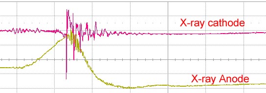
We closed the Prometheus chamber and filled oil on Wednesday, the oil became stable after one day. So I ran the system this morning, unfortunately the x-ray cathode pulse could not be synchronized with x-ray anode pulse. Keith and Bill suggested I should check the cathode thyratron CX1585, I replaced the thyratron and found the situation became wrose. I had to put the thyratron back. The picture shows the bottom of the Thyratron CX1585 in the x-ray cathode trigger box.This wave forms show (1) the x-ray anode signal without cathode pulse, the railgap were trigger randomly, I don't know what caused the x-ray cathode noise; (2) the cathode pulse without anode signal, the negtive cathode pulse looked well; (3) anode and cathode trigger pulses were applied to the x-ray gun, the cathode signal became worse, the noise followed the anode pulse, and the cathode pulse peak could not move forward to match the anode peak.

Monday, November 21, 2005

Maintenance of Rail gap switch 402000

Disassembled and cleaned the rail gap switch. The right picture shows how dirty of the rail gap switch. Because the SF6 gas flowed into the switch everyday, it might conterminated the box. The front window should be clear, however from here nothing could be seen inside. There are 4 pieces of this kind of spark gap used in our large aperture KrF Excimer Amplifier system. The 40 kV high voltages are applied to this spark gap in order to trigger the main high voltage pulses.

This is the cleaned rail gap switch. The front window looks pretty clear. The brass electrodes are shiny, the trigger rail is set in the middle of the electrodes.

We already cleaned and reassembled one spark gap, 3 pieces has been cleaned. Now I am testing the leakage of the finished one.

We installed 2 spark gaps in the North Bank, and one spark gap in the South Bank. The front windows of South Bank also were replaced with brand new windows. Below, the left picture shows the North Bank and the right picture shows South Bank.

Saturday, November 19, 2005

X Ray Gun 检测

今天终于还是把X RAY GUN取出进行检测。发现阳极头碳化很严重,左图为X RAY GUN的阳极绝缘头。每根阴极棒的电阻约为28K,经过初步清洗后,一边的电阻为7M,另一边为1M。基本上可以认为最近的问题差不多都是因为阴极棒的污染造成的。

另外在往外接X RAY GUN的时候,因为没有注意到CHAMBER里有一支架,所以拉的方位有点不对,下次时一定要注意。从右图中可以看到那个支架有两个小缺口,只有当X RAY GUN的两排螺丝与这两个缺口相对应时,X RAY GUN才容易拉出来。

Tuesday, November 15, 2005

准分子激光器X光预电离

上午基本上解决了阴极触发的问题,主要原因是250欧姆的充电电阻漏电,以及放电电极的接触不太好。更换电阻并拧紧电极接头后,阴极的触发变得比昨天稳定许多。但是后来发现X光的阳极触发变得十分不稳定,经检查发现是电压输入接头松动。

Monday, November 14, 2005

UV短脉冲激光在毛细管中的传输特性研究的初步实验

今天上午把一束UV飞秒激光输入到以前的空间滤波器,可能是因为焦距太短的缘故,出射光的光束质量非常差。下一步考虑是否用长焦距的透镜,目前手头有的最长的焦距为2米,准备更换以后再对光束进行测量。

下午,新订的DRY AIR到货,检测了X RAY GUN的阴极与阳极脉冲,发现两个脉冲还是不能重合,阴极脉冲总是晚于阳极脉冲。测量阴极与地之间的电阴为14 k Ohm,怀疑是否阴极板有问题?和KEITH商量后,他说可能还是控制电路部分的问题。

Tuesday, February 15, 2005

激光核聚变ICF(老文章存档)

追逐地球上的“太阳”
——核聚变研究状况及其新进展

中国科学院院士 王乃彦

  目前人类的主要能源来自煤、石油、天然气和用于核裂变的铀,但这些化石燃料的蕴藏量都是有限的,而其中有些化石燃料是很有用的化工原料,作为能源燃烧掉也十分可惜,而且还造成对环境和生态的严重污染。因此,人类把最终解决能源问题的希望寄托于核聚变能——被科学家们誉为“地球上的太阳”。
  聚变能是把两个质量轻的原子核(如氘、氚)聚合在一起释放出的能量,如太阳的能量和氢弹爆炸的能量;裂变能是重的原子核(如铀235、钚239)在中子作用下裂变成两个质量较轻的原子核时释放出的能量,如目前世界上核电站输出的能量和原子弹爆炸的能量。
  人类梦寐以求的聚变能是一种清洁、安全和资源蕴藏极其巨大的能源。它不产生二氧化碳、二氧化硫及其它有毒害的气体和颗粒,与太阳能、水能、风能和地热能相比具有不受时间和地域的限制的优点,与核裂变能相比,由于不存在裂变反应堆中的后备反应性,因此不存在临界事故的危险。核聚变的燃料是氢的同位素氘和氚,在海水中每6500个氢原子中就有一个氘原子,在地球上含有1013吨左右的氘,可以说氘的蕴藏是极其巨大的,几乎是“取之不尽、用之不竭”的燃料。氚是放射性同位素,在自然界中天然的氚极其稀少,可以通过中子与锂-6原子核的作用或氘吸收中子而产生。聚变燃料的释能本领比裂变燃料要大好几倍,比化石燃料则大上百万倍。
  核聚变固然具有许多优点,然而要实现聚变“点火”的条件是很高的,而且实现它的难度相当大。高温和满足劳逊判据是实现核聚变点火的条件。高温是使得原子核具有足够高的运动速度,以克服原子核之间的库仑位垒,实现核反应;劳逊判据的条件是参与核聚变反应的粒子数密度和能量约束时间之乘积必须达到一定值。1991年11月欧洲联合环(JET)进行了首次氘氚聚变实验,美国TFTR装置于1993年12月进行的氘氚聚变实验,其最高输出功率超过JET的结果达到了6.4兆瓦,并在1994年5月底的实验中达10.8兆瓦。
  引人注目的是,1991年欧洲共同体、美国、日本、俄罗斯协议联合设计建造一个国际聚变实验堆(ITER),预计在下世纪初投入运行,耗资约100亿美元。ITER每次放电持续时间约1000秒,聚变功率达1500兆瓦。该实验堆设计的特点是设备庞大,技术复杂,环形室的环面直径将达16米,环形室内的磁场由超导线圈所产生,它的建成对于开展全规模的聚变堆的技术及有关的材料研究无疑具有重要的意义。
  然而国际聚变实验堆并不是未来商用聚变堆的原型,在它上面并不能有把握地实现连续运行。它虽然是迄今为止计划建造的最大托卡马克装置,但面临着技术和经费的困扰,因而科学家们正在寻求缩小规模、节省资金的替代方案。最主要的设想有下面几种:认为在科学家还没有完全掌握建造聚变堆的知识的情况下,不应该把装置建得过于庞大,应该具有一定的灵活性,这种想法主要在意大利的实验室中进行,他们已经在较强磁场的较小装置上成功地约束了热等离子体。由于国际聚变实验堆上等离子体约束性能并不十分理想,需要进一步提高,日本JT—60SU的超导装置的初步概念设计是探索先进的约束模式。也有人提出开发具有超级约束特性的全新磁结构,以实现比较经济的聚变堆。在磁约束聚变中除了托卡马克装置外,德国、日本都在建造大型的超导仿星器,在仿星器的实验中等离子体的约束性能及稳定性和相同规模的托卡马克装置上的结果相比都并不差。
  核聚变的另一重要途径是惯性约束聚变。它的基本原理是在一个约为几个毫微秒的时间内,将能量约为几个兆焦耳的脉冲激光束、粒子束均匀地照射到氘、氚燃料的靶丸上,由靶丸表面物质的溶化、向外喷射而产生的向内的聚心的反冲力,将靶丸物质压缩至高密度和热核燃烧所需的高温,并维持一定的约束时间,释放出大量的聚变能。以激光束为驱动器的惯性约束聚变称为激光核聚变。目前国际上最大的激光聚变装置是美国劳伦斯利弗莫尔实验室的NOVA装置,它有10束激光,在波长三倍频的情况下,输出激光的能量达40千焦耳,该实验室曾利用核爆情况下产生的强X射线间接驱动惯性约束聚变,取得了十分鼓舞人心的结果。美国计划花11亿美元建造一个国家点火装置(NIF),它是钕玻璃激光器,输出激光能量为1.8兆焦耳,靶上激光脉冲功率峰值达5亿兆瓦,预计可以达到点火,计划在2003年左右建成。
  我国核聚变研究在国际上具有先进水平,真正接近模拟堆芯等离子体的磁约束聚变装置。现在已建成的HL—1M和HT—7两套中等规模的托卡马克装置,分别建立在成都中国西南物理研究院和合肥中科院等离子体物理研究所。中国环流器新一号(HL—1M)除具有离子回旋共振加热、电子回旋共振加热手段外,还增加了中性束注入加热手段,配置了低混杂波电流驱动系统和多发弹丸注入系统。HT—7是一台超导磁体托卡马克装置,它的放电时间在第一阶段长脉冲状态可达5秒,在准稳态状态下可达60秒。在这两台托卡马克装置上都取得了重要的科研成果。目前HT—7u(HT—7升级)和具有良好性能偏泸器的HL—2装置正在建造。
  我国激光惯性约束聚变的研究起步在国际上也是比较早的。在60年代即已进行用激光打氘冰靶出中子实验,以后主要在增大激光的能量和提高光束品质方面努力,到80年代神光Ⅰ装置问世。目前在上海高功率激光物理联合实验室正在建造神光Ⅱ,它有八路激光,总能量为6.4千兆,三倍频后的输出能量约3千兆。北京中国原子能科学研究院正在研究一台氟化氪准分子激光装置,用于研究短波长高功率激光和等离子体的相互作用。
  当今世界,各国科学家正在积极研究和探索,追逐地球上的“太阳”,预计下世纪中叶核聚变能将开始投入商业应用。

(《人民日报》1998年12月1日)


神光II系统输出激光能量全面达标。脉宽1ns,八路总能量大于6000J,最大每束800J;能量平衡5%;光束质量优于3.5倍衍射极限;四束激光大能量穿380μm小孔,平均穿透率85%;器件经几个月运行,没发现激光介质损伤。
神光II装置首轮物理实验获得重大突破。首轮直接驱动内爆出中子物理实验于4月7日首发激光发射就获得2×10⁹个中子产额;这一实验又重复数次,最高获得3.9×10⁹个中子;这次理论、实验、器件、诊断和制靶研究水平的综合检验,标志着我国激光核聚变研究总体水平跨上一个新的台阶。
高功率激光发展相关的系列单元支撑技术,包括神光II、神光III装置所用的高质量大功率氙灯、大尺寸高质量磷酸盐激光玻璃和超高强度、超高性能的激光薄膜都通过了863-416专家组的阶段验收,获得高度评价,主要性能达到并部分超过国外先进水平。

惯性约束聚变是利用高功率的激光束或粒子束辐照聚变燃料,聚变燃料被压缩T高温高(5千万度以上)密度(600g/cm^3)发生聚变。由于这个过程与氢弹有相似T处,惯性约束聚变研究从一开始就是处于保密状态。也由于惯性约束聚变与氢有关,几个核大国在二十世纪60年代就开始了各自的研究。1994年,美国PLawrence Livermore National Laboratory解密了他们在90年代以前的实验结果。值得国人自豪的是,中国是开始这方面研究的最早的国家之一:已故杰出的核理学家王淦昌院士在1964年就提出了激光聚变的设想。然而限于中国的国力,尽管起步不晚,我们在这种大科学工程方面的研究不可避免地还是走在了别人的前面。中国进行惯性约束聚变的主要力量有两个:一是位于四川绵阳的中国工程T理研究院,另一个是位于上海的上海光学与精密机械研究所。目前,中国最大的激光聚变装置“神光II”号(8kJ/1ns/1μm/8束)就位于上海,另外一台小型的激光装置“星光II”(150J/1ns/0.35μm/1束)则位于绵阳。从装置的规模来看,我国要落后世界最高水平20年左右。尽管如此,中国人在激光聚变的很多领域,尤其是技术领域还是做出了很多值得称道的工作:如已故邓锡铭院士在1980年代初期发明的一种光束均匀化技术已经被国际认可,被称为“上海法”或“邓法” 山东大学生长出大口径的非线性光学晶体(KDP);Nd玻璃的大批量生产,等等这些关键技术的突破,无疑为增强中国的综合国力做出了贡献。中国计划在绵阳建造更大的激光装置“神光III”,尽管它的规模比美国目前在建的NIF(National Igniton Facility)仍然要小许多,但通过“神光III”的建设中国必定会在大口径光学加工、大口径电子光学系统方面的技术力量和技术储T得到极大的加强,而且必然会带动一批相关产业的发展。

Monday, February 14, 2005

近场光钳与单分子操作

近场光学与近场光钳方法是近年国际上近场光学研究领域从理论上提出的新方法。这种方法特别适合于生命科学单分子研究。

传统光钳方法已经用于生命科学的基础研究。1999年《Science》上发表了6篇关于生物单分子研究的文章,显示出传统光钳在生物单分子研究中的最新成果。科学家研究了分子马达的动力学和运动学特性,发现它是以步进方式运动;通过对单分子进行扭转、旋转、拉伸等操作研究其力学特性和生化动力学;拟建立分子动力学和分子力学研究体系,对DNA分子进行力学向分子机械学、分子水平仿生优化设计等一系列研究。

完成上述研究的最基本的手段是光钳。其基本原理是利用了聚焦光场中梯度光力效应及光场超微颗粒相互作用形成"光阱","捕获"光场中的微粒进行操作。最近日本科学家采用双光钳实现了DNA分子(2纳米直径)的扭转、打结,这表明分子操作达到相当高的水平,为细胞内蛋白纤维相互作用等分子力学的研究开辟了新的途径。

然而,由于传统光钳是建立在远场衍射受限原理之上的,其所形成的"光阱"受到原理性限制,最小空间尺度约为半波长,即300纳米左右。实际工作时通常在生物样品端部附着微米胶球,光阱"捕获"胶球,通过对胶球的操作实现对纳米尺寸生物分子的操作。

而近场光学从基本原理上突破了衍射极限实现了直接真实空间纳米成像。近场光钳所形成的"光阱"空间尺寸有可能达到纳米量级。近场光钳具备了直接对单分子操作的可能性,其潜在的应用在于操作生物纳米颗粒和生物单分子。同时使分子运动的动力学、生物化学等过程的荧光检测及分子取向等信息的单分子荧光检测和其他光谱检测成为可能。
近场光钳将可能成为最强有力的生物单分子操作工具。

光学光钳技术

激光光钳是一种利用高斯激光光束的梯度压力将微粒移到激光束焦点附近的装置。微粒处于按高斯分布的激光束中时,由于光场强度的空间变化,光束对微粒产生一种梯度压力,驱使其移向光束中心,并稳定在那里。激光束如同一?quot;钳子"抓住微粒,随其移动,可以无损地操纵如细胞、细菌、病毒、小的原生动物等生物粒子,为微生物学家、医学工作者提供新的有力工具。为了减小对微粒的影响,多采用近红外激光。德国生物学家用激光在卵子细胞周围的保护层(蛋白质和碳水化合物)上打孔,利用光钳将精子抓住并送入卵细胞,从可以帮助那些缺少尾巴或无法游动的精子与母卵细胞结合,从而大大提高了体外受精的成功率。

分子马达定向运动机制研究

分子马达是广泛存在于细胞内部的具有小马达功能的酶蛋白生物大分子。生命活动中的许多基本过程都是基于分子马达的运动,如真核细胞内沿细胞骨架系统的物质输运, DNA复制过程中DNA解链过程, 细胞有丝分裂期间染色体的分离过程以及肌肉收缩过程等等。分子马达运动所需能量来自于它所催化的三磷酸腺苷分子(ATP)水解所释放的化学能。它将化学能直接转化为机械能。 对分子马达的研究不仅具有分子生物学上的意义而且有助于未来人们设计化学能直接转化为机械能的装置。

目前实验上利用光钳技术[1]在体外无损的情况下直接观测单个分子马达的运动,得到了许多重要结果[2],与此同时,理论研究也成为分子生物学和统计物理研究中的热点之一[3]。我们以非平衡态统计物理为基础提出了温度涨落驱动分子马达定向运动模型[4]和具有内部自由度的分子马达模型[5]。下一步的工作将充分考虑分子马达的结构和其他实验结果,建立更符合实际的分子马达模型,从而探索分子马达定向运动的机制。
参考文献:
[1] A. Ashkin, Proc. Natl. Acad. Sci. USA, 94(1997)4853.
[2] J. T. Finer, et al. Nature, 368(1994)113; K. Svoboda, et al.. Nature, 365(1993)721.
[3] P. Reimann, et al. Phys. Rev. Lett. 79(1997)10; T. Duke and S. Leibler, Biophys. J. 71(1996)1235.
[4] Yu-Xiao Li, Physica A238(1997)245.
[5] Yu-Xiao Li, Physica A252(1998)382.

作为一种重要的辅助技术,光镊在单分子科学中也占有重要地位。光镊的基本原理是利用光学梯度力形成的光阱来俘获和操纵微观物体。我们知道,光实际上是电磁波,当它产生空间分布不均匀的电场和电势时,电势梯度会在电介质上产生一个作用力。更直观的,我们把光看成光子流,光入射到物体表面,光子的部分动量转移给物体,会形成光压。光场的性质决定了物体的受力,通过适当的设计光场分布,我们可以把物体俘获在一定的位置,这种光场分布称为光阱,如高斯光束本身就是一个二维光阱。当然,通过移动光束我们可以方便地实现迁移或翻转俘获物体。因为这种光学技术在另一个尺度实现了传统机械镊子的功能,所以被称为光镊技术。在单分子实验中通常把生物分子样品联结到介质小球上,通过 用光镊技术俘获和操纵介质小球来达到操纵样品的目的。

到80年代后期,基于光的力学效应和激光冷却技术,发明了光镊技术,人们可以对单个 DNA分子施以皮牛顿(10-l2牛)级的力作用。因此,在近几年,Nature 和Science 刊登出许多论文,报道单个DNA分子在光镊拉力作用下的非线性弹性拉伸应变实验结果。这为研究单个DNA分子构型提供了实验基础,从而逐渐形成一门软物质凝聚态物理中的新学科——单分子生物学或单分子物理学。
生物大分子的自由能是由kBT来表征,这里kB是玻尔兹曼常数,T是温度(一般是室温)。生物大分子的空间构型的尺度是在纳米量级,这就容易理解对生物大分子的作用力必须是皮牛顿级的。单分子生物学与单细胞力学也可以称为皮牛顿力学,这也是从事激光冷却的诺贝尔物理学奖获得者朱棣文被吸引到单分子生物学的实验研究中的原因。

Sunday, February 13, 2005

微波激射与激光的诞生

作者 David Lindley, bon 译

注释:值此国际物理年(2005年)之际,《物理评论》杂志编选了反映爱因斯坦成就的相关文章,以纪念爱因斯坦奇迹年(1905年)诞生100周年。

摘要/内容:激 光如今已无处不在 ,从超市收款机、CD播放器到眼科诊所,到处都可以发现它的身影。1954和1955年出版的《物理评论》首次对激光进行了介绍。激光由微波激射器 (maser,也译作:脉塞)发展而来,而微波激射器(maser--microwave amplification by stimulated emission of radiation,受激辐射引起的微波放大的英文首字母缩写)的产生,正是基于爱因斯坦约40年前(1916年)极具先见的理论。然而,从理论到应用 的道路绝非一帆风顺,科学家们融合了诸多学科的研究成果,才将这些理论上看来十分简单的装置真正展现在人们的眼前。

二战后,雷达科学家与物理学家合作,希望寻找到在厘米波段范围内产生电磁辐射的方法。物理学家希望利用该技术来研究分子结构。研究发现,当分子中的原子键在不大相同的构形间发生振动时,原子键通常会吸收或放出厘米或毫米波段的辐射。

但是雷达中的真空管和相关装置无法产生亚厘米波段的辐射。20世纪50年代初,正在纽约哥伦比亚大学工作的查尔斯-汤斯(Charles Townes)突然想到,只要能使大量分子同时发射,分子本身就可以成为绝佳的发射器。汤斯早期对微波波谱的研究帮助了他后来的工作。

早 在1916年,爱因斯坦就从理论上预言了受激辐射的存在??即一定频率的电磁波可以“刺激”受激原子或分子,使之跃迁到低能级并产生更强的电磁 辐射。1947年,哥大的威利斯-兰姆(Willis Lamb)和罗伯特-卢瑟福(Robert Retherford)就利用受激辐射来放大氢分子产生的辐射,以更精确地测量特定分子跃迁的频率。

汤斯对微波技术十分熟悉,很快想到了实现受激辐射的办法。他设想将腔体内大量受激分子以合适的尺寸聚集,一些分子放出的射线反射回来与其它分子相互作用,这样就使得受激辐射不断增强,通过腔体与分子之间形成的反馈机制将信号急剧地放大。

汤 斯和同事在1954年制成了世界上第一台微波激射器(maser)。他们将一束受激的氨分子射入谐振腔内,由于腔内分子辐射产生受激分子,而受 激分子进一步增强辐射,并提供源源不断的受激分子,因而辐射得以自持。第一台微波激射器只产生厘米尺度的辐射,所以功率很小,仅为十毫微瓦左右(10-8W)。但值得注意的是,在发射谱上其辐射能量呈现为极细锐的谱线,这也就意味着辐射的频率十分单一,仅含一个波长而没有其余波长的干扰(单色性好)。

不 少理论物理学家曾认为汤斯设想的装置根本无法实现。可它的的确确实现了!于是研究者纷纷仿效制造,并开始在原来基础上加以改进。1958年,汤斯和新泽 西州贝尔实验室的阿瑟-肖洛(Arthur Schawlow)曾计划制造一种在红外和可见光区工作的激射器,但直到1960年第一台光激射器才真正问世??这也就是我们所说的激光(laser)。 汤斯也因其在微波激射器和激光领域的贡献分享了1964年诺贝尔物理奖。

由于不同团体对专利权的争夺,激光的发展还遇上过不少官司。麻省理工的伯纳德-伯克曾在哥大见到过第一台微波激射器,他的话颇令人深思:“汤斯无意将它保密,相反,它向未来的研究者敞开了欢迎之门。”


参考资料:
Molecular Microwave Oscillator and New Hyperfine Structure in Microwave Spectrum of NH3
J. P. Gordon, H. J. Zeiger, and C. H. Townes
Phys. Rev. 95, 282
(issue of 1 July 1954)

The Maser--New Type of Microwave Amplifier, Frequency Standard, and Spectrometer
J. P. Gordon, H. J. Zeiger, and C. H. Townes
Phys. Rev. 99, 1264
(issue of 15 August 1955)