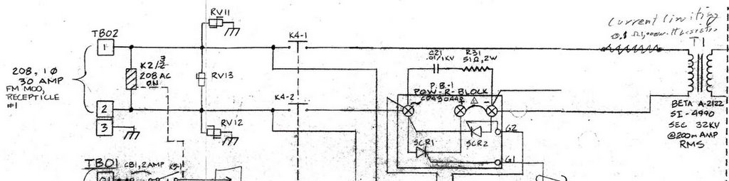
However, the 30 kV for thyratrons still could not be applied. Mike and I checked the low level circuit and did not find anything wrong. Then we firstly measured the voltage cross relay K4, it's ~205 V as the relay switched on. We were afraid that the SCR could not be controlled, so we monitored the voltage crossed SCR, it's ~200 V when the control panel H.V. switch was off. The value became to 0 V as the H.V. switch was on. It means the SCR and control system working correctly, but the H.V. meter show the voltage was 0 V. We will check transformer and rectifiers tomorrow.
No comments:
Post a Comment