I received the SCR and relay this morning, I installed them and test the system again. However, the high voltage still could not be controlled. Mike helped to check the circuit board again.
Craig loaned us the used computer (400 MHz, Pentium II, better than our old one), which can be used to grab the wave froms from the oscilloscopes. I installed Tektronix WaveStar and successflully obtained the wave forms, much faster than the old machine.
Tuesday, February 28, 2006
Friday, February 24, 2006
Relay P40C42A12D1
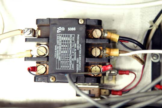 According to the yesterday's current and voltage measurement, we concluded that there must be a position broken to block the current flow through transform primary. The most possible is the relay K4 on R03 board. So I removed the relay to check.
The relay K4 module is P40C42A12D1-120. I found the pins were burnt due to the high current.
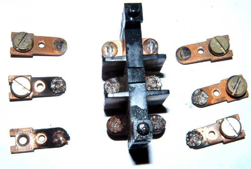 One pole was almost melted together, and could not be detached. This broken relay effected the SCR normal operation, might cause SCR breakdown. I have not found the relay from Newark, they suggested to replace it with TYCO 1423254-6. However there was no in stock, we have to order at least 9 pieces if we really want to buy. So I ordered the similar module -- P40P42A12P1-120. Although it's not the same relay, we can replace the old pins with new ones. I think it's the fast way to fix the problem.
Thursday, February 23, 2006
Measuring the current
Before we receive the ordered SCR, I found an old SCR in the lab (don't know it's good or not). I installed it and tried to measure. Unfortunately, this SCR was bad, I could not monitor the current even I could measure the input voltage. I used the current clamp to measure the current on the X-ray gun high voltage power supply, I obtained the current waveform. The high voltage power supply for x-ray gun was designed using the similar design of M03.
Tuesday, February 21, 2006
SCR CM341290
I contiuned to test the SCR part today. When I turned on the system, I could measure the firing angle signal from C-2154 board. But I have not measured the high voltage. After warming up several minutes, even I did not send the firing angle signal, I could monitor the high voltage. This phenomenon might be caused by the bad SCR?
I found an interesting paper about the inverse parallel thyristor written by Dr. Henry E. Payne.
http://www.payneng.com/AN11-18/AN11-18.htm
Thyristor Theory and Design Considerations(PDF)
I found an interesting paper about the inverse parallel thyristor written by Dr. Henry E. Payne.
 Figure. 1 |
| |
 Figure. 2 |
http://www.payneng.com/AN11-18/AN11-18.htm
Thyristor Theory and Design Considerations(PDF)
Monday, February 20, 2006
ERATRON FPE 202 D30
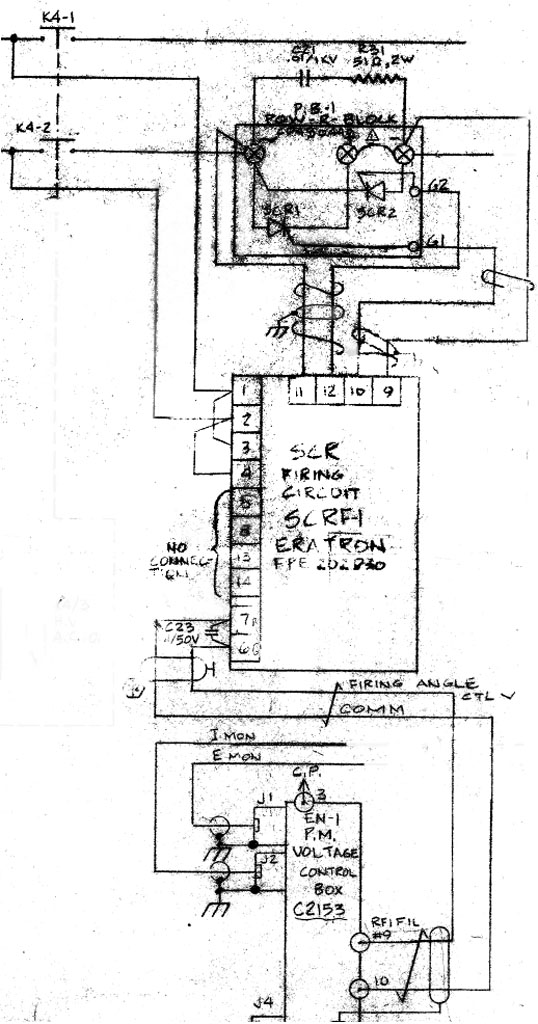 We removed the SCR control unit -- ERATRON FPE 202 D30 to check. We could not find anything wrong of this part.
The SCR is Powerex CM341290 (Voltage 1.2 kV, Current rating: 90 A). I measured the firing angle and high voltage current.
Friday, February 17, 2006
SCR control unit
Mike helped to fix the C-2154 board, we measured the firing angle signal independently and found it very well. However, the high voltage could not be controlled. Even the firing angle signal has not been sent to the SCR control unit, there was a high voltage output. We could measure the current as soon as switched on the high voltage without the firing angle. This caused the whole system breakdown, we must check the SCR and its control unit next Monday.
Wednesday, February 15, 2006
Keep checking C 2154 Board
 I replaced the broken relay K1 on R03 module as soon as I got the ordered relay. But I did not monitor the high voltage. We could not detect the firing angle signal from C-2154 board. Mike checked the board again and found pin 7 of A4 mechanically broken. After we replaced the A4 chip, we tried to run the system. This time, we could measure the firing angle, but the high voltage monitor still showed zero. We disconnected the firing angle output on C-2154 board and sent a pulse wiht 3 V, 500 ms to the SCR control unit, then we could see the high voltage monitor worked well. It means the SCR and control unit is okay. So we will continue checking the C-2154 board.
Tuesday, February 14, 2006
High Voltage Control Module R03
I checked the R03, measured the signal of pulse modulation H.V. reference voltage (frequency). I have not found anything wrong. The frequency can be tuned from 0 to 10 kHz, which will be converted to voltage 0 to 10 V DC by chip L451 on the C-2154 board. Now we are afraid the feedback or SCR control unit may cause the high current. Mike suggested to send a 800 ms square pulse generated by function generator to test the SCR control unit. If the system running well, we can confirm it's feedback to effect the current. Unfortunately when I installed the circuit board in R03, one leg of the relay K1 accidently was broken. The relay model is Potter & Brumfield R10-E1P4-115V, I have ordered it from OnlineComponents.
Friday, February 10, 2006
C-2154 PCB repaired
We checked the Pulse modulation PC Board and replaced the Zener diode D9 and capacitor C1. Then I put back the board to test the system, unfortunately the system could not run in the right condition. I could not adjust the high voltage yet. When I monitored the frequency input Vref, I found there was only a noise signal. The reason of this may be the extend board or the signal from Control Rack R03.
Thursday, February 09, 2006
Pulse Modulation Control PCB
 I already replaced the SCR on high voltage power supply board M03, also checked the high voltage diode rectifier SCH20000 yesterday. But I could not tune the voltage later, I found there was not correct output at the Firing Angle at pulse modulation control PCB. That trigger pulse voltage was less than 1 V.
Mike helped me to check the board. We measured the pulses on pin 1 at A4, pin 7 at A4, pin 6 at A1 and pin 6 at A2. We found it's feedback to decrease the voltage of Q1 input.
Tuesday, February 07, 2006
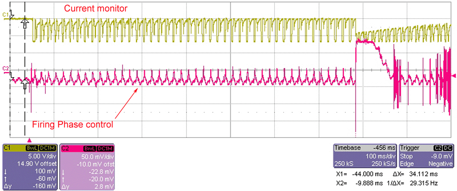
10K Ohm resistors burned again
 It's weird that the 10K Ohm resistors were burned again. This time were second resistor and third one. The current must be drained too much somewhere, so that the resistors were burned again and again. We measured the current which passed through the whole system, here we named it Imon. Now Imon only can keep about 300 milliseconds. I also measured the firing angle from Box 2270, that waveform looks strange, too.
 I found some waveforms which
 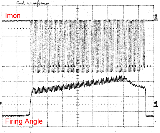 were recorded on Jan 10th, 1995. The current should be kept about 800 milliseconds, and the firing angle looked like a flat pulse. From those pictures, there was one waveform mostly like the above one, it marked "Drawing high current". There was another note on the other waveform, "Swayback should not be here. Indicate I separate changing cycles due to only 1/2 of the SCR firing block working".
We already checked the 2155 circuit board in the box today, it's very good. We will check the 2154 board, which generate the firing angle signal.
Monday, February 06, 2006
Unltra-high Intensity Ti:Sapphire/KrF* Excimer Hybrid Laser System
1. Introduction
Based on the chirped pulse amplification (CPA) technique [1] and the Kerr-lens mode-locked Ti:sapphire laser [2], a laser intensity of 7x10²⁰ W/cm2 has been achieved by the solid state laser system. In order to reach this intensity, a laser system with extremely high peak power of 1500 TW (440 fs, 660J at 1054nm) [3] is required, which leads the system very complicated and expensive. Since the laser intensity is inversely proportional to the square of the wavelength, the given high intensity can be reached using the ultraviolet (UV) laser with much lower peak power. The main method to produce laser pulses in the UV spectral region is using rare gas-halide excimers. Unlike in solid state laser, excimer lasers with appropriate heat exchange can avoid thermal effects such as thermal lens; also due to the less optical distortion in the gas medium, the excimer laser has an advantage to give better beam focusability. By combining compact femtosecond laser with KrF* excimer laser chain for amplification of the converted UV pulses, our old Ti:Sapphire/KrF* excimer hybrid laser system [4] is upgraded. The new system can produce the laser pulse with a peak power of 4 TW and focused intensity up to 2 x10²⁰ W/cm2.
2. System configuration
The Ti:sapphire/KrF* laser system is composed of the front end and the large aperture KrF* excimer laser amplifier.
The front end consisted of three main parts (Fig. 1). The first part is a commercial Ti:sapphire solid-state laser system (Spectra-Physics Lasers Inc., CA), which generated a 100-fs pulse train at 745 nm with a repetition rate up to 500 Hz. The output pulse energy is around 600 mJ. The second part is using the polished BBO crystals with 0.8 mm and 0.24 mm thickness for frequency doubling and tripling respectively. A 1.1 mm thickness MgF2 wave plate is inserted between the crystals to compensate the group velocity delay after frequency doubling. The output energy from the tripler is about 120 mJ with ~100 fs at 248 nm, which is sent the third part to seed the excimer preamplifier. The excimer module is arranged in 4-pass off-axis geometry in order to reach the optimal conditions for amplifying femtosecond pulses [5]. The output from the first double-pass excimer amplifier is spatially filtered by a 150-mm-diameter pinhole in a diffraction-limited manner in the vacuum pipe. A pair of grating is placed after the first 2-pass amplifier to compensate the dispersion before propagating through the amplifier chain by adding a negative pre-chirp to the laser pulse. The output of the pre-amplifier is up to 20 mJ with ~120 fs pulse duration.
After the pre-amplification the 248 nm pulse is collimated and expanded to a 10-cm diameter beam using a 4-power reflecting telescope of Dall-Kirkham design. The final seed pulse is injected into a large aperture KrF* excimer amplifier [6]. This powerful amplifier is designed to operate at relatively low pressure and low gain in order to reduce wave-front distortion and amplified spontaneous emission (ASE). The final pulses exhibit the average energy of 600 mJ at repetition rate of 0.4 Hz. A portion of final laser pulse is sent to the frequency resolved optical gating (FROG) device for the measurements of pulse duration and phase shift. The pulse duration is ~200 fs, and the phase shift is around several mrad.
2. Focusability
In order to calculate the laser intensity at best focus, the focusability of the seed pulse after it passed through the large aperture excimer amplifier was measured. The 10-cm-diameter seed beam was sufficiently attenuated so that no air breakdown or the beam self-focusing occurred. The beam was directed onto an off-axis parabolic mirror of 20 cm focal length. The focal spot of this f/2 optical system is imaged by a 40 times UV microscope objective (Partec GmbH) onto a CCD camera (Watec-502B) without the cover window.
The beam profile at the image plane of the microscope objective is shown in Fig. 2. The focal spot size of the 248-nm seed pulse is ~1.5 mm in diameter, which is about a factor of 1.5 times larger than the diffraction-limited spot size.3. Conclusion
This upgraded system finally generates 200-fs pulse duration, the 1.5-mm-diameter focal spot size, and the laser energy of 600 mJ, which gives an average intensity of ~2?1020 W/cm2. To our knowledge, this system generates the highest laser intensity at 248 nm. We will use this laser to develop high brightness hard X-ray source from a Xe cluster target for application in biological microimaging [7].
References
[1] P. Maine, D. Strickland, P. Bado, M. Pessot, and G. Mourou, “Generation of ultrahigh peak power pulses by chirped pulse amplification,” IEEE J. Quantum Electron. QE-24, 398-403 (1988).
Friday, February 03, 2006
Systerm testing
After changing the thyratron on the south side, we tried to run the system today. I ran the system under 15 kV, it still ran well after one and half hour. No any click sounds occurred from the south side bank, even that changed thyratron looked a little bit different from the others.
Thursday, February 02, 2006
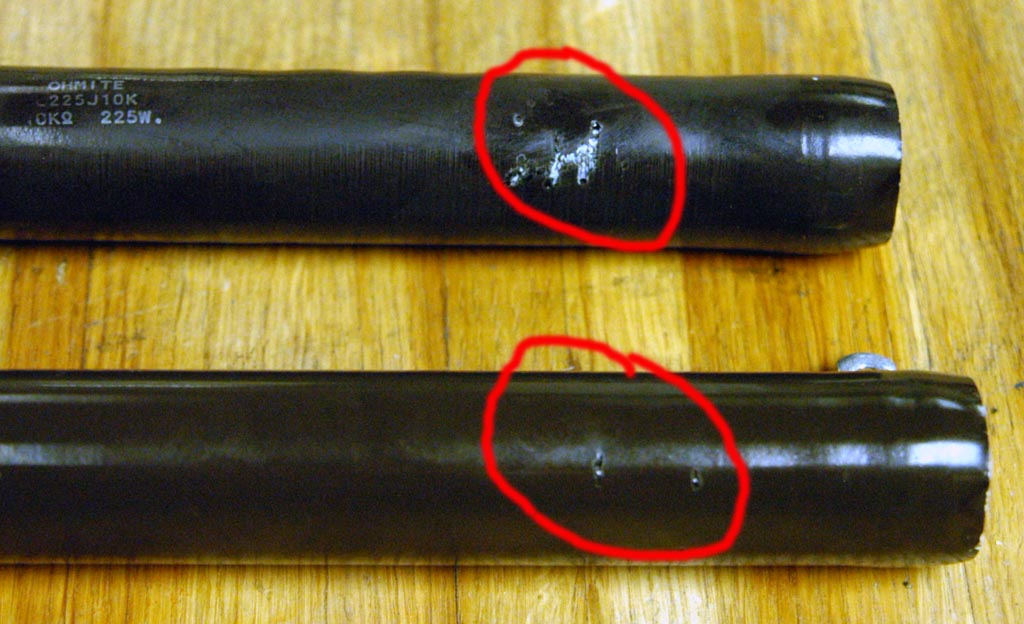
Changed south side thyratron CX1622
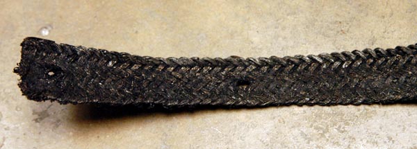 We concentrated on the south side trigger today. We found one of the thyratrons on the south side was triggered unstably. Inside that thyratron, the small arcing was observed during the period
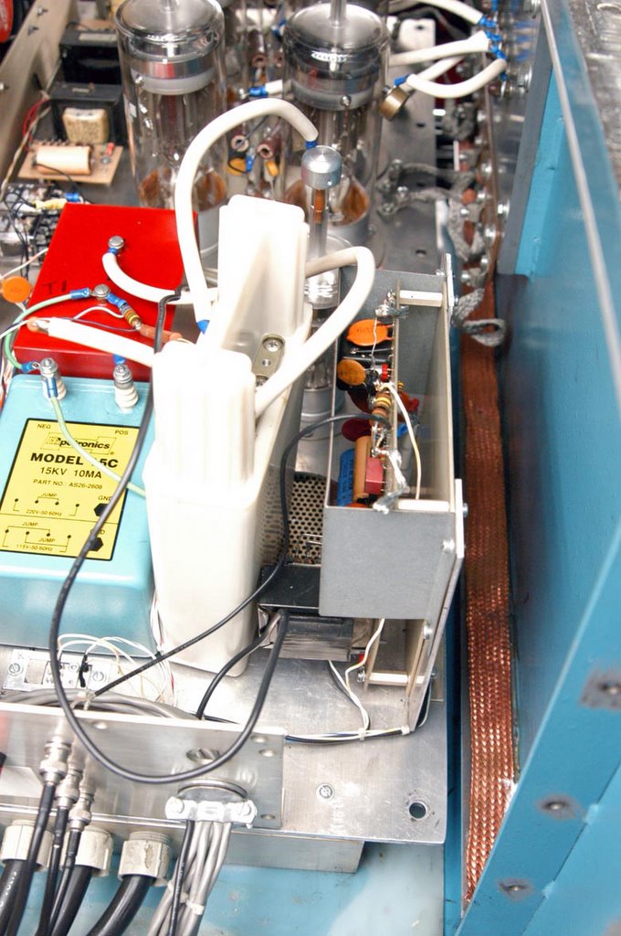 between two trigger signals. Mike suggested to replace that one immediately. When I lifted the thyratron board, I am surprised to find the conduct tape was so dirty.
This conduct tape connected the thyratron board to the ground, that's why the sparks on the plate were always obtained. So we removed the old dirty conduct tape and put a brand new copper tape.
Because we don't have new thyratron CX1622 at hand, I installed a used one which was probably still good.
Wednesday, February 01, 2006
Keep Passivation
I continue to passivate the Prometheus, except south side sometimes missing fires, upon to now
everything sounds very well. Now I am tracking the south side transformer primary, secondary,
filament 1st stage and 2nd stage, I hope to solve this random trigger problem soon.
everything sounds very well. Now I am tracking the south side transformer primary, secondary,
filament 1st stage and 2nd stage, I hope to solve this random trigger problem soon.
Subscribe to:
Posts (Atom)