Showing posts with label TWINAMP. Show all posts
Showing posts with label TWINAMP. Show all posts
Tuesday, December 12, 2006
1st Spatial Filter leakage
Mike helped us fix the vacuum pump for the first Spatial Filter of TWINAMP, however we found there was a big leak from the vacuum pipes. We checked the pipes step by step, firstly found one of the O-ring was broken, then small holes around the vacuum pipes. After replacing the O-ring and gluing the leaks, the vacuum reached about 10 mTorrs.


Thursday, November 30, 2006
Timing delay jitter problem
Unfortunately, we could not resynchronize the TWINAMP using the two separated trigger pulses. I think the large RMS jitter from BNC 7010 digital delay generator makes the synchronization failure. So I replaced the BNC generator with SRS DG-535, the TWINAMP ran steadily. DG-535 has only 50 picosecond RMS jitter. The best way to eliminate this jitter is to control 4 channels of DG-535 by computer. If we buy a GPIB-RS232 converter from NI, it's easy to communicate with only one DG-535 for switching on or off the trigger signals("out 1" and "sync out").
Monday, November 27, 2006
New timing setup for beam stabilization system
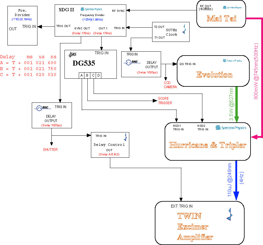 The beam stabilization system needs control signals from SDG II "out 1" and "sync out", so I have to change the timing again. I already modified the timing for the front end before (on July 7th), but I did not consider to trigger the Pockcel and TWIN AMP separately. Now I have to insert one more delay box such as BNC delay generator in order to trigger the TWIN AMP.
The beam stabilization system includes one CCD camera and one chopper, both of them also need the TTL pulses to trigger. The pulses from BNC #1 to trigger CCD, #2 to trigger the beam chopper.
Tuesday, November 14, 2006
Heater and reservior voltage for TWINAMP
The TWINAMP could not be triggered by internal pulse correctly but only by external signal normally yesterday. By my early experience, the problem was caused by the thyratron heater and reservoir voltages. We measured the heater voltage(V_H) from the power supply output, which is about 10.2 VAC. When I decreased this voltage down to 9.4V (the minimum adjustment), the TWINAMP ran well. We also measured the voltages from thyratron side.
On May 1st, I set the Heater and Reservoir voltages: V_H=11.35V, V_R=8.35V. On Oct. 18, 2005, we set the voltages: V_H=7.05V, V_R=7.49V.
| Power Supply Output | Before filter | Before Thyratron | |
| V_Heater(VAC) | 9.30 | 7.80 | 7.50 |
| V_Resevior(VAC) | 7.78 | 7.48 | 7.48 |
On May 1st, I set the Heater and Reservoir voltages: V_H=11.35V, V_R=8.35V. On Oct. 18, 2005, we set the voltages: V_H=7.05V, V_R=7.49V.
Wednesday, November 08, 2006
Leak from Alumnium box
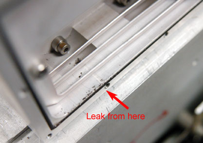 We cleaned all TWINAMP windows, filled 400mbar F2 + 1400mbar He for leakage detection last night. We found the pressure was dropped by 50mbar for the long tube, and we could smell pungently. Because the o-rings for window and PVDF plate were changed last month, maybe the gas leak came from the aluminum box connected to the window frame. We found some black grain in the aluminum box. The o-ings were changed immediately.
Monday, November 06, 2006
Repolished the TWINAMP long tube windows
We removed t he winodws from TWINAMP lone tube, and found they were very dirty. The small black grains on the surface like last time. There was a thin gray film on the inside surface when we looked the windows at the grazing angle. This film could not be removed by normal optical cleaning method. So we tried to repolish it using 1 micro power. After repolishing, the surface looked very smooth.
Tuesday, October 31, 2006
TWINAMP window holder design
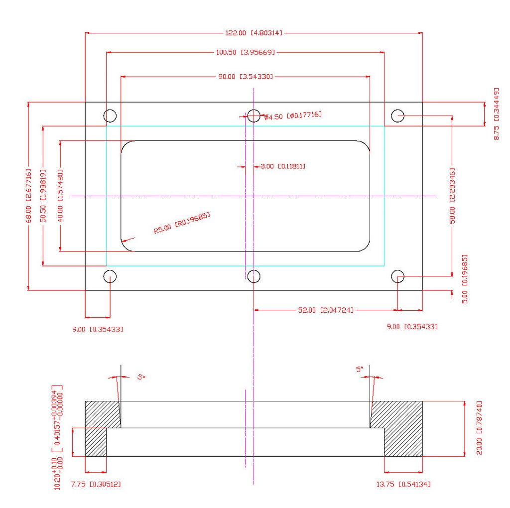
Because the thickness of the MgF2 window for long tube was different, the old holder can not be used. Excepting the thickness, the other dimensions should not be changed anymore. The material: Aluminum Plate (Al Zn Mg Cu 1.5). Surface: good quality (milled profiles)
Monday, October 30, 2006
Leybold TRIVAC D16B pump
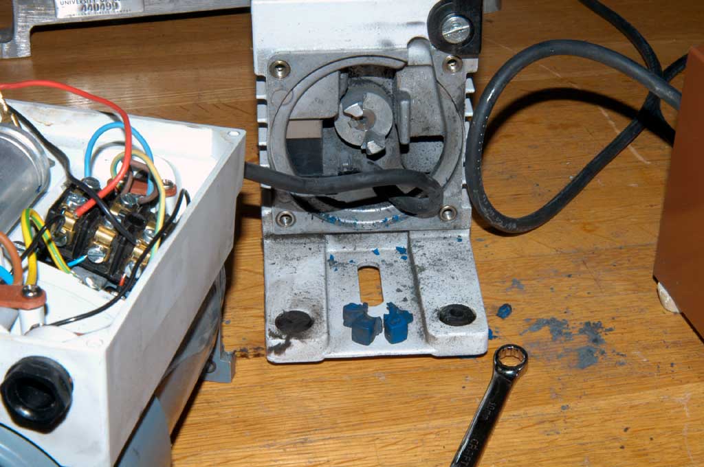 We used the rotary vane pump to vacuum the first spatial filter for TWIN system, this pump could not work two weeks ago. At first, we guessed the start capacitor was broken, however the pump did not work any more even we changed a new capacitor. Mike helped to separate the motor and the rotary vane, he found the motor worked well. The problem was the spider coupling was broken.
Tuesday, October 24, 2006
FROG measurement using new CCD camera
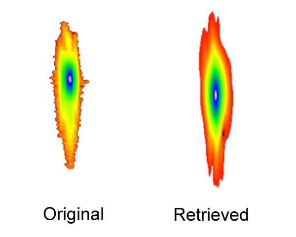 We used the new FLI back illuminated CCD to take the FROG picture. I found this new CCD camera very sensitive to the UV light compared with our old CCD. For the old one, we had to expose about 5 seconds to take Hg I 248 nm line, for this new one, it's only about 30 ms.
When we were taking the FROG images, the signal was very strong. I had to use a ND filter (~0.005 transimission) to attenuate the light. The retrieved data is almost match the raw data. But for the old CCD camera, it's not well to match these data.
Thursday, October 12, 2006
Vacuum pump for first spatial filter
We found the vacuum pump for TWIN first spatial filter does not work. I guessed it's caused by the motor start capacitor, unfortunately this kind of cap was from Europe.
Wednesday, September 06, 2006
Windows cleaning and O-rings changed
I removed the windows of both tubes. The windows of the long tube are a little bit dirty, maybe the energy dropping was caused by the leakage. The most possibility is the leak from the windows. Firstly it's diffcult to take the window from the holder, I dropped some ethonal into the gap between window and the holder, the window became loose and was easy to remove. I cleaned windows carefully. Unfortunately I found there was a light breakage inside the window, we should order new window for the long tube.
I installed all windows in the afternoon, and made the passivation for both tubes. Before my leaving I filled the Helium into the chambers by 1500 mbar for leakage checking. I will continue to passivate the tubes.
I installed all windows in the afternoon, and made the passivation for both tubes. Before my leaving I filled the Helium into the chambers by 1500 mbar for leakage checking. I will continue to passivate the tubes.
Tuesday, September 05, 2006
TWIN windows became dirty again
After the labor day, we tried to continue the experiments. So I filled the new gases into the TWIN excimer amplifier this morning. The output energy of the front end was 34.7 mJ, Alex already used this beam to align the target and x-ray spectrometer. Unfortunately, the energy was dropped to 7.7 mJ suddenly in the afternoon, I found there were small dust grains on the long chamber windows, which was similar to the status two weeks ago (on Aug. 22th). I cleaned the same windows on May 10th (http://xysong.blogspot.com/2006/05/twin-dirty-windows.html). It is very strange that the windows became dirty frequently. I guess the filter was dirty or something wrong inside the long tube.
Monday, August 21, 2006
Tightening LLG-TWIN thyratron plate and ground plate
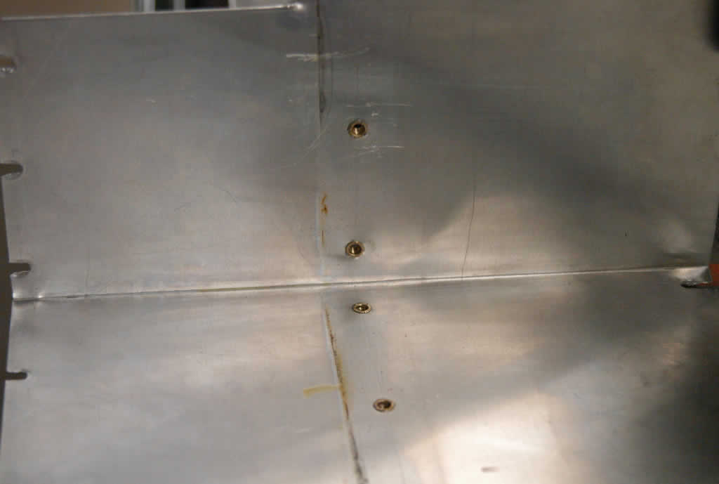 Last month, we found the arcing problem when running the LLG-TWIN excimer amplfier, I put a teflon plate for preventing the sparks. Today the arcing happened again, I am afraid the isolation plate could not really avoid the arcing. With Randy and John's helps, we removed the alumina plate and found the spark traces on plate of thyratron side.
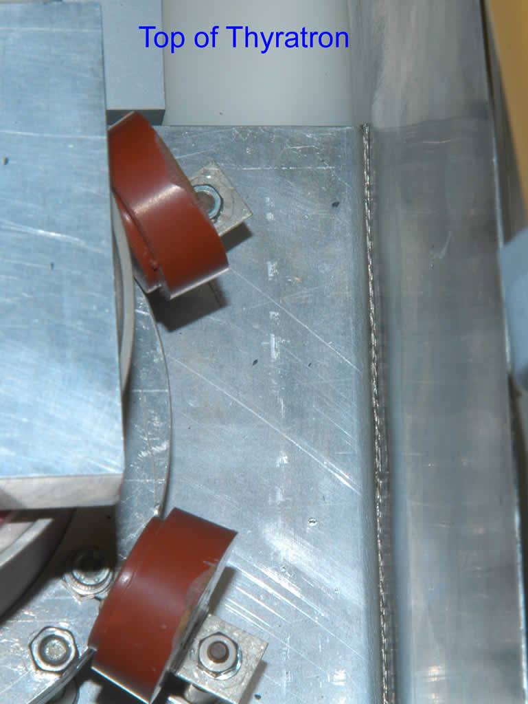
We polished the plate surface and punched a new hole for conbine the
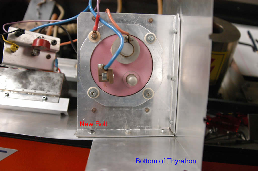 plates tightenly. A wire braid was inserted between the plates in order to avoid the arcing.
Finally we fixed the arcing problem, however the output energy was still low and the beam quality was very bad. When I checked the lone tube windows I found there were some dark grains on the window surface. I want to open the chamber to clean them tomorrow.
Friday, July 21, 2006
Changed the H.V. cable
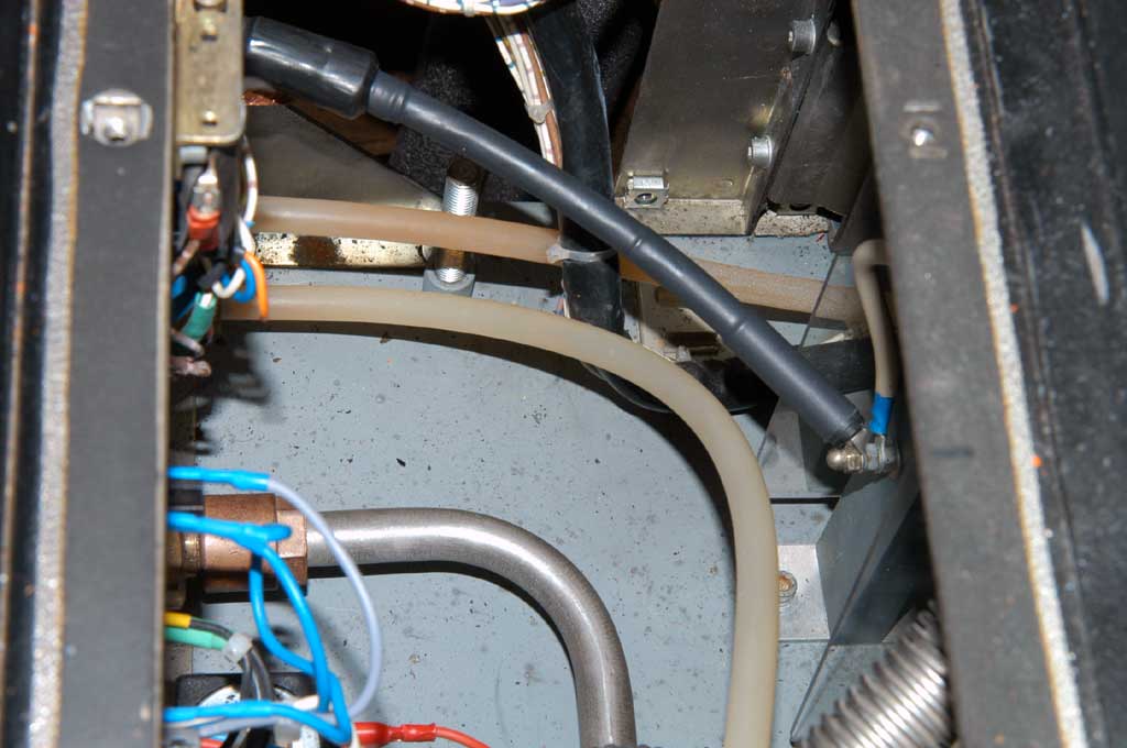
I found a spare cable in the lab, so I just replaced the burnt cable with it. But the plug body connected with the power supply was borken, so I replaced it with the plug body of the burnt cable.

Wednesday, July 19, 2006
TWIN H.V. cable burnt
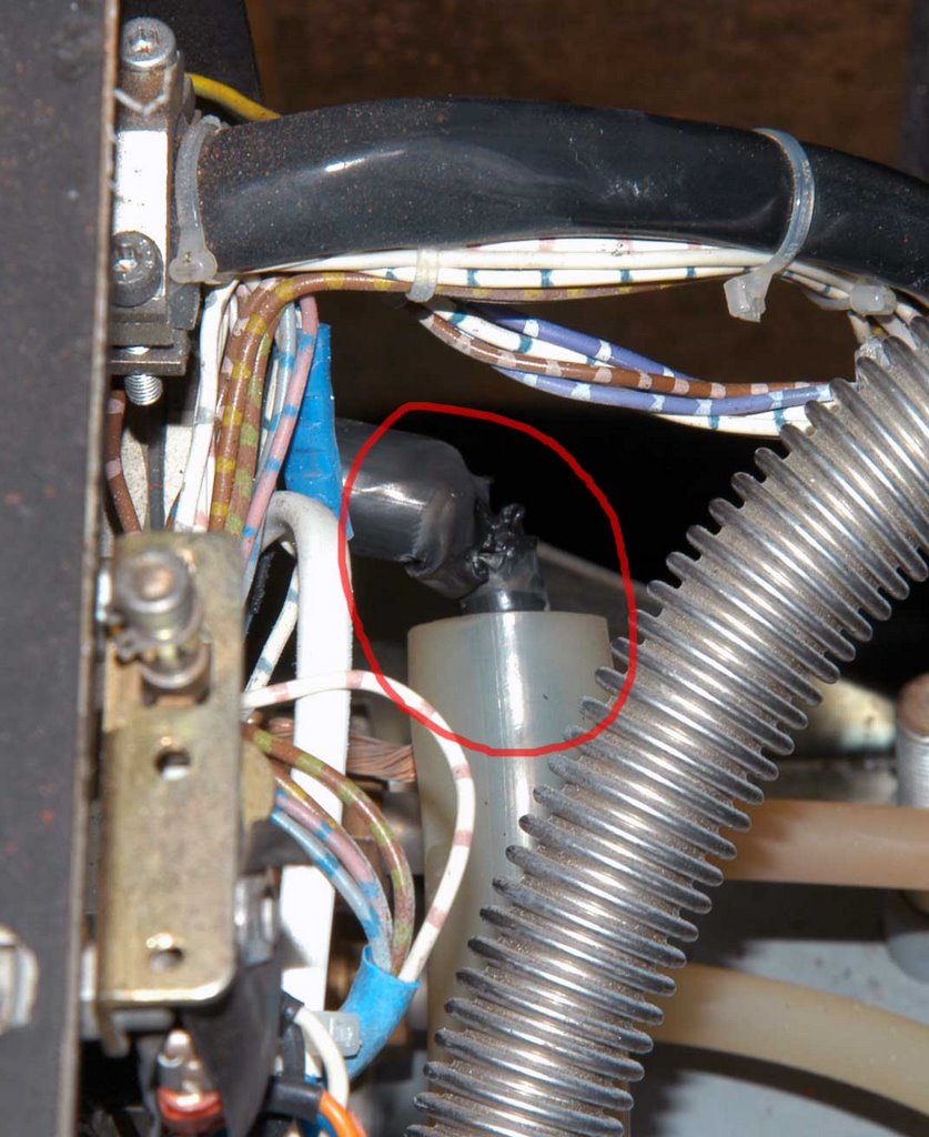 In the afternoon, the TWIN excimer amplifier suddenly stopped firing after running for half hour. I found the power supply light became red, the light was off after pressing the reset button. Then I pushed the H.V. button and Laser button, I heard a buzz sound inside the excimer chamber. I energized gradually to the amplifier, the voltage reached 12 kV, the buzz appeared again then the system shut down immediately.
I opened the chamber, and turn on the system to check where the buzz came from. I found the high voltage cable was burn, the buzz was from the broken cable. The arcing from the cable caused the fail in high voltage increasement.
Tuesday, July 18, 2006
Arcing from LLG-TWIN excimer inside
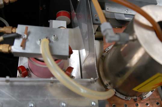 When I ran the TWIN excimer amplifier, I could hear the crack sound inside the chamber. This phenomenon was happened before, which was caused by the spark from the Thyratron plate and ground plate. I put two picece of plastic sheet to isolate them. Probably the sheet became dirty or they were too thin. The Thyratron plate should be tightened with the real ground plate in order to avoid the spark, however it will take several days to remove the plate to drill the holes for tightening. The simple way is to replace the isolating plate with a new teflon plate. After replacing, the system ran well.
Friday, July 07, 2006
Modification of front end timing
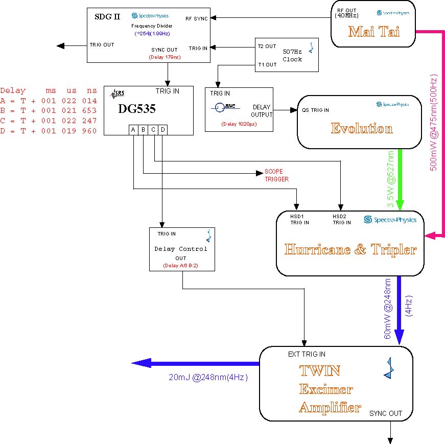 In order to synchronize the seed pulse and Prometheus ASE, I tried many ways without using more delay control equipments. But all the attempts were failed, I have to consider change the front end timing. By studying the old system timing, I found a 10ms delay was added to the CAP pump Q-switch laser, I could copy this setup for our new system. So I inserted a 1ms delay by using BNC delay controller, then replaced the original delay controller from LLG with SRS DG-535. The channel A of DG-535 was used to switch Pockell in and channel C for Pockell switch out. The output of channel D was used to control the excimer control box.
We will have extra 1 ms time delay for the Prometheus trigger and target nozzle controller.
Thursday, May 11, 2006
Cleaning the windows
I removed the windows of the long tube, and found some small black grains on the inside surface. I carefully cleaned the window and reinstalled them immediately. After that I passivted the both tube for about one and half hours, the long and short tubes emitted red light. Finally I measured energy of the TWIN excimer with 45 mJ, and the beam pattern looked better than before.
Wednesday, May 10, 2006
TWIN dirty windows
I tried to measure the laser energy, however I found the output energy of LLG-TWIN was very low. This seed beam could not be amplified up to ~500 mJ after passing the Prometheus. The pre-amplified beam patten looked very bad, I checked the windows and found they are very dirty. So I want to clean them tomorrow.
Monday, May 08, 2006
Trigger channels changed
I tried to trigger channel B (M02) of DG-535 firstly using the SDG II TRIG OUT signal and set up the other channels as below:
A=B+1.57 us
B=T+30 ns
C=B+30 ns
D=B+1.3 us
Under this setup, the laser pulse output is same as the last Friday.
A=B+1.57 us
B=T+30 ns
C=B+30 ns
D=B+1.3 us
Under this setup, the laser pulse output is same as the last Friday.
Subscribe to:
Posts (Atom)