Wednesday, March 29, 2006

Ordering EUROTHERM 7100A SCR controller

We found a SCR Power controller similar to our SCR controller. The product is from EUROTHERM.

The Model 7100A is a new range of economic SCR Power Controllers for use with resistive, infrared or inductive loads. This unit features integral heatsinks with analog voltage or current inputs for precise control.

Our ordering code is 7100A/100A/240V/230V/XXXX/MSFU/PA/XXXX/0V5/ENG/NONE

Monday, March 27, 2006

Transformer for X-ray Gun H.V. Power Supply burnt

Mike replaced the IC chips and transistors already, then we send a control signal pulse to measure the SCR output. The waveforms looked well, so I install the SCR controller in the X-ray Anode control box.

We tested the whole system in the afternoon, unfortunately the x-ray gun could not be run correctly. The x-ray anode high voltage was not monitored, while the high voltage connected to the Thyratrons was pretty good. After running a few minutes, I smelled the smoke. Then I found the transform connected between SCR and X-ray anode H.V. power supply was burnt.
===========================
AUTOTRANSFORMER P-8634
Primary ---- Line Cord
230V 50-60Hz

Secondary ---- Receptacle
115V@400VA

STANCOR Chicago, IL

Friday, March 24, 2006

Data acquiring system

We received the Tek 2024 scopes this afternoon, John helped me to install them in the rack. I connected these 2 scopes and TDS 520 to the computer with GPIB cables. The data can be acquired in real time, even it's not as fast as the scope response. I think it should be enough to obtain the data at 0.4 Hz. Actually we don't need to acquire the data for every shoot, we only need some special data for diagnostics. Previously Keith only used two channels scope to track the signals, which could provide enough information. Now we are using 10 channels to measure the signals.

ERATRON FPE 202 D30 Circuit board

Mike already removed all IC chips and put the sockets for pluging easily. He wants to replace all the IC chips from IC1 to IC8 and transistors Q1 to Q3. Until now we received the chips except IC4 and IC5.

No.Chip/TransistorFunction
IC1TL084CNLow Noise JFET Quad OpAmp
IC2CD4093BE14-Dip Quad 2In Schmit Trgr
IC3LM741CNOperational Amplifier
IC4MC14027BDual JK Flip-Flop
IC5CD4046BECMOS Micropower Phase-Locked Loop
IC6TC084CNLow Noise JFET Quad OpAmp
IC7LM555CNTimer
IC8CD4082BECMOS Dual 4-input AND gate
Q1J113N-Channel Switch
Q2MPS A13NPN Darlington Transistor
Q3MPS A13NPN Darlington Transistor

Thursday, March 23, 2006

Changing the Beam Stabilization Setup

It's difficult to recover the beam stablization setup if we move it, so I changed the setup. Kevin helped to make the plate and the posts. I aligned the beam into the beam expander and make sure the expand beam finally enter the target chamber correctly. This time we only used one mirror to steer the beam to the CCD camera, I will test the imaging system soon.

Monday, March 20, 2006

Repairing the SCR controller

Mike contacted PLC Center requesting the circiut drawing of SCR controller, unfortunately the company did not have any drawing. Like Mike doing, they only can replace the chips one by one to test the logical output. Up to now, Mike already ordered the chips and transistors for the circuit repairing.

Friday, March 17, 2006

beam stabilization system

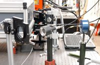
Regarding the installation of the LLG beam stabilization system at UIC it can be
stated that
1. The optimizations works properly.
2. The closed loop control works in a standard configuration i.e. beam control is achieved with a stationary 500 or 4 Hz pulse train respectively.

However, some problems encountered during the installation schedule have to be solved:
1. The motherboard of the PC delivered by LLG is defect.
The fastest solution, we suggest is that you buy a identical mainboard and replace the old one on your own. Regarding the compensation of your financial effort, we should discuss with Klaus Mann and Uwe Wachsmuth next week.
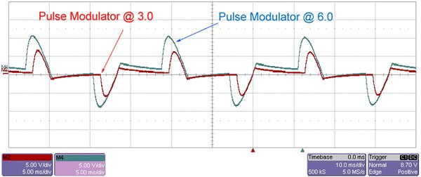
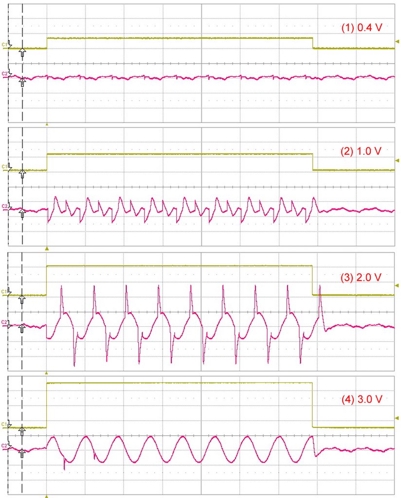
2. The contrast ratio of the pre-amplified pulses and the frontend ones are approximately one to two orders of magnitude too high. Thus, at an attenuation level sufficient to perform the closed loop control of the frontend beam,the CCD chip gets damaged after illumination with very few (app. 10) amplified pulses.
Actually the chip shows 7 damaged pixel, but this virtually does not hit the performance,as we use only a 1/16 part of the chip, so a non damaged part can be selected.
The best solution we think would be the use of a variable attenuator, based on a mechanical shutter. This shutter should have a contrast ratio of 100, and could easily be triggered by the 4Hz Trigger of the TWIN amplifier without any software support. This could be done in Goettingen, but doing it by yourself in Chicago will be much faster.
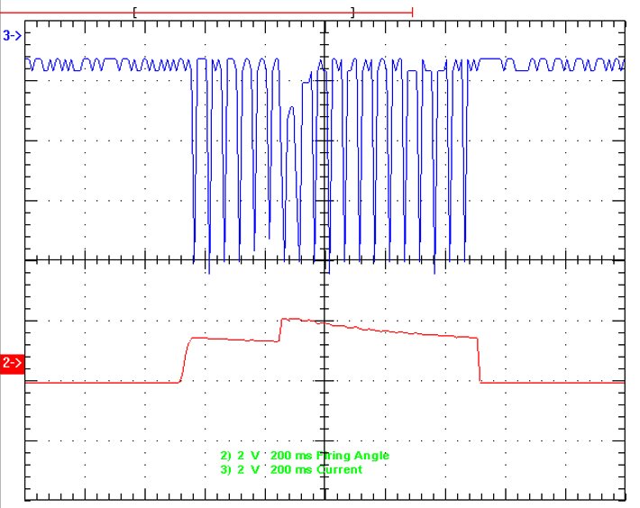
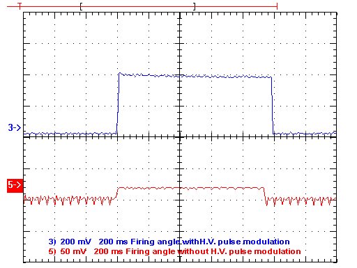
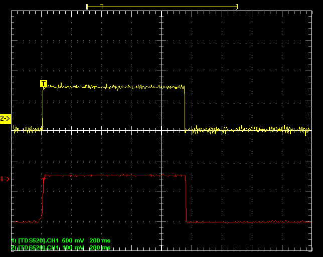
3. The closed loop control based on switching the frondend from a 4Hz to a 500Hz mode for a short time interval between two consecutive 4Hz TWIN pulses does not work. Part of this failure seems to be the high overexposure mentioned above. Another reason is probably some internal logical software bug. - However, the mode switching works, and closed loop control has been achieved without amplifier, although the software fails to set the correct values the the pulse timing schedule.

This problem should be solved in Goettingen during the next weeks. An updated version of the program may then be tested by Dr Song, who will have my full support via email or phone.

(Reported by Bernd Schaefer)
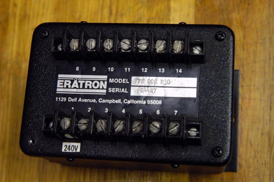
Tuesday, March 14, 2006

Testing computer control system

We connected SDG-II to computer with RS-232 port.

Monday, March 13, 2006

Installing laser beam stabilization equipment

Dr. Bernd Schaefer came to help us install the equipment of laser beam stabilization today. I will assist him. I ran the TWIN excimer amplifier, its output energy reached ~30 mJ. By sending less than 1% transparent beam behind a reflected mirror to the equipment, we could monitor the laser beam profile. The problem is after the same ND filter the transparent of seed beam is too weak compared to the pre-amplfied beam.

The computer was sent from Germany, we could drive it by 115V power supply. I ordered a 110V 500W power supply for computer.

Thursday, March 09, 2006

Exchanged SCR Phase Controller

Because the X-ray anode preionizer system used the same high voltage control design as thyratron discharging. We exchanged the SCR phase controller ERATRON FPE 202 D30 for troubleshooting.

This time, I can control the H.V. pulse for thyratrons, but cannot control the x-ray anode H.V. pulse. We confirmed that SCR controller cannot be run well. When the H.V. pulse modulator set scroll was tuned from 3.0 to 6.0, the current waveform at transformer primary was followed to change. The voltage meter showed the H.V. changed from 5 kV to 15 kV.

I also monitored the transformer secondary current I_mon and SCR firing angle. We finally concluded that SCR firing phase controller was not well, Mike helped to replace some problematic chips. ERATRON has been not existed, it's impossible to buy the same controller. The similar controller may be found to replace. A company named PLC Center provide repairing service. We would like to send this block to them for repairing if we cannot do it.

Wednesday, March 08, 2006

Failure of H.V. pulse control

Like before, we failed to control the high voltage output. When I turned on the H.V., even without the modulating pulse (it means no firing angle signle applied to SCRF-1), we could measure the high current through the transformer primary. So I disconnect the primary of big transformer and connected them to a step down (40:1) small transformer. Then we measured the wave form from the secondary. We always saw the wave form (see the picture) which could not be adjusted.

Tuesday, March 07, 2006

SCRF-1 pin 12

We received the 451L chip this morning. Then we installed it on circiut board. The right picture shows the firing angle wave forms with/without H.V. pulse modulation. When I tuned the voltage amplitude, the firing angle voltage was followed to change.

Unfortunately, there was not any output yet. I checked the wires and found pin 12 on SCRF-1 was losing. Maybe this caused no high voltage.

Friday, March 03, 2006

Frequency voltage converter AD 451L

Today we combined the C-2154 circuit board and SCR together to check, we found pin 13 at C-2154 was not connected to common point. This caused the output of firing angle floating. After we fixed it, the firing angle pulse was changed. The test result was shown on the right picture, the wave 1 is the pulse without out common, wave 2 is the pulse after fixing.

Then I installed C-2154 and SCR back into the system for testing, unfortunately the high voltage could not be measured yet. The difference is that there was no high voltage output even after running for a couple of minutes. So we wanted to remove the C-2154 card to check again, however, we accidentally took off the card with the power on. We found the power was still on even I turn off the switch. Then we found the frequency-voltage converter AD-451L does not work, it must have been damaged when we removed the circuit board. I already ordered 451L from Newark. We will change the chip and fix the switch next Monday.

Thursday, March 02, 2006

Check SCRF-1 and SCR independently

I removed SCR Firing Circuit SCRF-1 (ERATRON FPE 202 D30) and SCR (Powerex CM431290) from M03 board. Mike connected them (circuit shwon as yesterday) to check them independently. The firing angle input was a pulse with amplitude of 0~5 V and duration of 140 ms, pin 7 of SCRF-1 connected to ground. An 1:4 step down transform was connected to SCR out port. When we tuned the firing angle amplitude, we measured the transform secondary wave form. Actually we have not found anything wrong of these measured parts, the output could be adjusted by tuning the firing angle amplitude. We will send pulses generated by C-2154 board to SCRF-1 for checking the output tomorrow.

I also filled the new gases into the LLG-TWIN excimer and ran the front end system.

Wednesday, March 01, 2006

SCR gate 2 and gate 1

We firstly disconnected the transform primary to measure the SCR gates G1 and G2. The picture of wave forms is shown below. During measurement we found the firing angle was changed from pulse to continued voltage. I thought this might be caused by the feedback.

In order to send a correct control pulse to SCR controller, we sent a pulse generated by the function generator. This time we connected the transform primary, the waveform was shown as left bel. We found only SCR gate 2 pulse was modified, the gate 1 was not changed anymore.