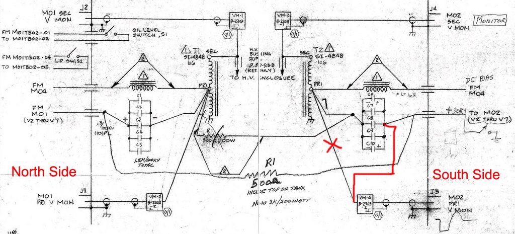
I pumped the oil from top tank and checked connects inside the oil tank
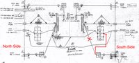
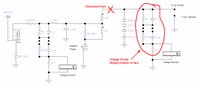
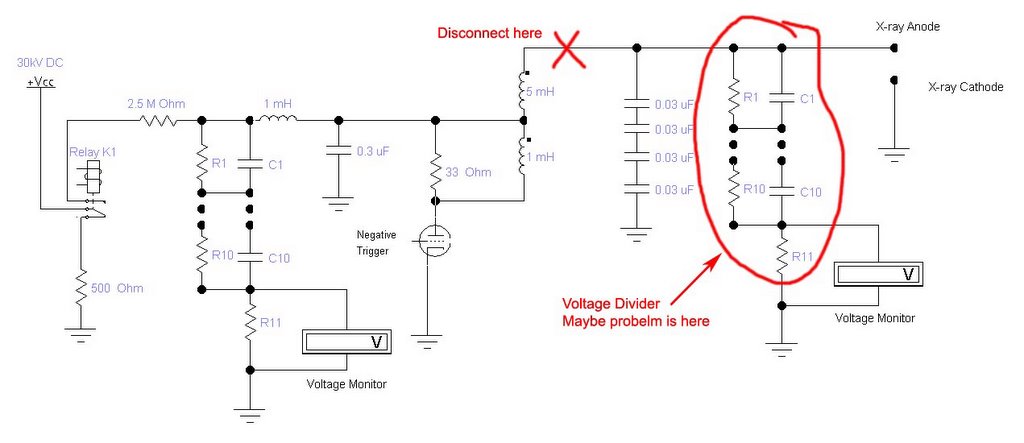
carefully. I found where the problem was finally. Then main point is the voltage monitor connection. This voltage divider should be connected after the charging capacitors(black line), but it was put before them(
red line, wrong connect). It's impossible to charger the caps, the voltage were drained down through resistors before charging the caps. I remembered that I installed the north side by myself after cleaning, and the south side was connected by other guys. I have not checked the wire connection after installing whole system. This gave me a lesson seriously, which is that I must check the circuit carefully anywhere and anyhow.
The system ran well in the afternoon except the x-ray anode randomly triggered. Mike suggested measuring the anode high voltage power supply independently. Firstly we only gave the power to 30kV HV power supply, in this case we don't worry
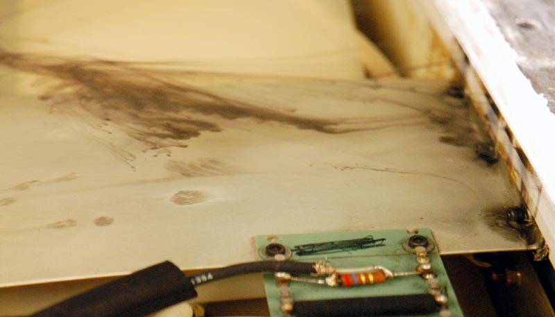
about the low level trigger. When I increased the voltage slowly to 10kV, the current meter showed about 1~2 mA steadily. From the circuit drawing, the current should keep lower than 0.5 mA. We guessed the resistors might have problem. Then we disconnected the cable between transformer and 4 caps (shown as in the picture) and checked the front end circuit separately. This time we increased the voltage gradually to 30 kV, the current always was kept around 0.2 mA. Now it's pretty sure the breakdown was came from either caps, x-ray anode voltage divider or x-ray anode bar. The 4 caps are brand new, and just were replaced last month. They can be excluded. We will check the voltage monitor for x-ray anode tomorrow.
I also changed the O-ring for oil circulation system. I found the O-ring became crispy so that caused the oil leak from the seal slit. The O-ring model is 261, Kevin helped me to find it from the work shop.
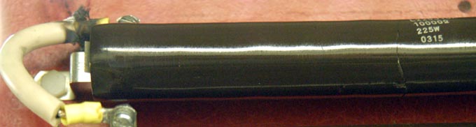
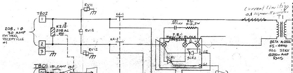
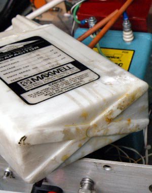 Keith suggested to decrease the voltage by 15 kV for passivation. I tried this way and found the system worked well, and the red light from the chamber looked homogeneous. However the south side randomly missed triggers, I can hear the click from the south thyratrons and see the sparks inside the thyratrons. I thought maybe the trigger circiut board send the noise, so I removed the circiut board. Casually I found the capacitor connected between thyraton CX1585 and CX1622 was very dirty, there was some yellow liqud leaked from the capacitor. I changed this dirty one by a clean one.

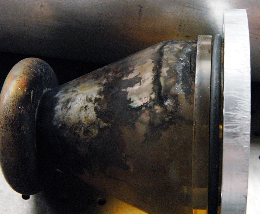


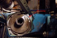
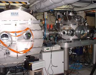
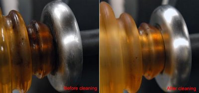 Mike and I measure the resistance between x-ray anode and ground using the megohm meter, it was about 5.8M Ohm as applied 1kV test voltage. It's definite that the front or back bushing was not good insulated. So I took out the anode bar to check the front bushing. I found the epoxy insulator looked very dirty, there was oil track on the surface. I think the silicon oil might leak inside the x-ray gun when we installed the anode bar. We cleaned and repolished the bushing, it looked more cleaning(shown as the top picture).


