The laser system ran very well today. The front end output a laser beam with about 26 mJ energy. After the Prometheus amplifier, the energy reached about 360 mJ as energizing 25 kV high voltage. Today the total shots is 1218, no misfire happened. The filament was shut down in the beginning, I could hear the click from the filament relay, after turn on again, the problem disappeared.
Because the nozzle was changed, I adjusted the timing delay for optimizing the Xe(L) outputs. Alex took many spectra from the target side.
Wednesday, August 30, 2006
Tuesday, August 29, 2006
Seed beam focal spot measurement
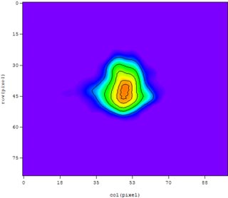 The seed beam was sent to the target chamber after expanding beam size from 3 cm diameter to around 10 cm diameter, then it was focused to the smaller spot by a Parabolic mirror. We are using the 248 nm coated paroblic mirror with 20 cm focal length, so the focal spot under the diffraction limitation is about 1.2 um.
In order to measure the focal spot, we put a 40X microcope objective lens behind the spot. A CCD camera without a window to record the spot image, the CCD size is 510x492, the pixel size is 9.6 um x 7.5 um. After calculation, the focal spot is about 2.9 um x 3.8 um.
Friday, August 25, 2006
Monday, August 21, 2006
Tightening LLG-TWIN thyratron plate and ground plate
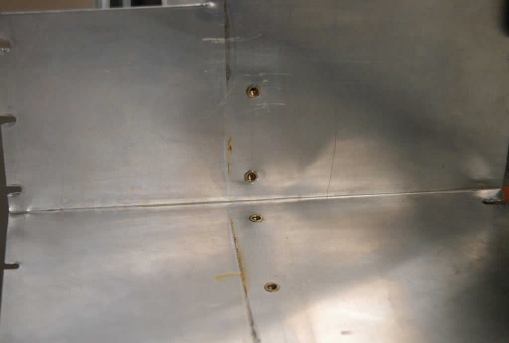 Last month, we found the arcing problem when running the LLG-TWIN excimer amplfier, I put a teflon plate for preventing the sparks. Today the arcing happened again, I am afraid the isolation plate could not really avoid the arcing. With Randy and John's helps, we removed the alumina plate and found the spark traces on plate of thyratron side.
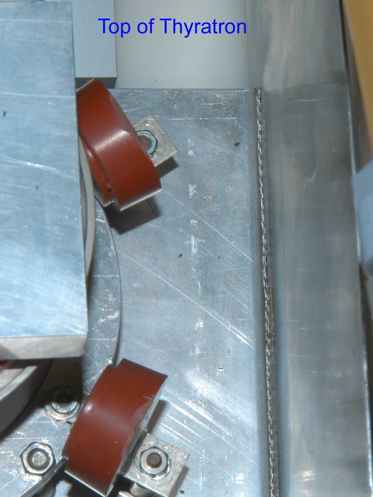
We polished the plate surface and punched a new hole for conbine the
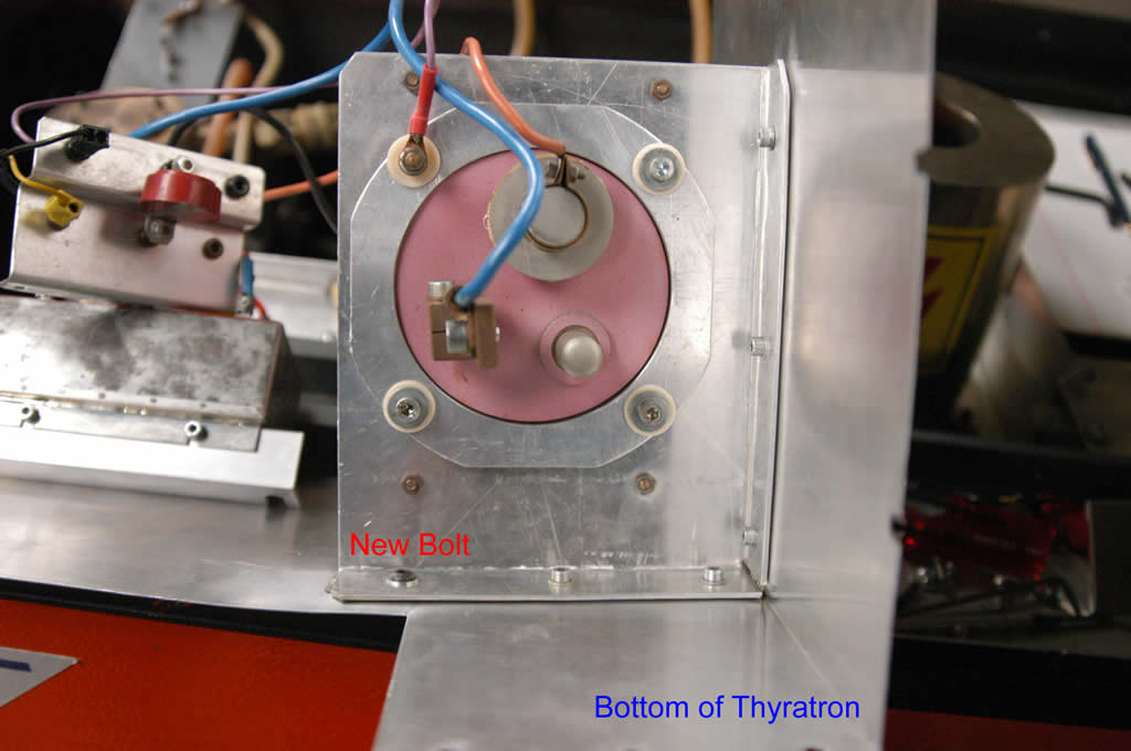 plates tightenly. A wire braid was inserted between the plates in order to avoid the arcing.
Finally we fixed the arcing problem, however the output energy was still low and the beam quality was very bad. When I checked the lone tube windows I found there were some dark grains on the window surface. I want to open the chamber to clean them tomorrow.
Wednesday, August 16, 2006
Front-illuminated CCD or Back illuminated CCD?
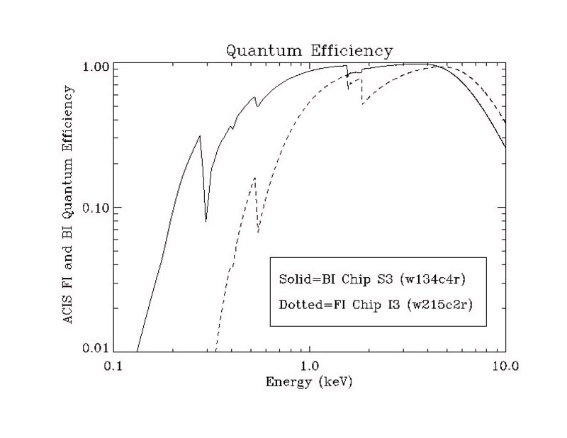 A conventional CCD consists of a sandwich of semiconductor layers overlaid with a network of "gates", electrodes which serve to transfer charge from one pixel to another as the device is read out. At low energies (E<1>5 keV). due to photon loss through the front of the back-illuminated device.
Comparison of QE of front- and back-illuminated CCDs. The lack of gate structure at the exposed surface of the back-illuminated device, combined with its reduced physical thickness, results in improved QE for energies <3>5 keV), due to photon loss through the front of the back-illuminated device.
copied from http://cxc.harvard.edu/newsletters/news_05/node11.html
CCD detectors are not able to convert all of the photons that strike the surface into electrons for a variety of reasons. Quantum efficiency (QE), which describes the ability of the CCD to turn photons into a useful form of output, is basically the ratio of incoming photons to those photons actually detected by the CCD. The typical range of efficiency is from a few percent up to 90%. Efficiency will also vary with the frequency of light (color) observed. Front-illuminated thick chips are not as sensitive to blue light as they are to light with longer wavelengths.
Interested link:
CCD glossary
Subscribe to:
Posts (Atom)