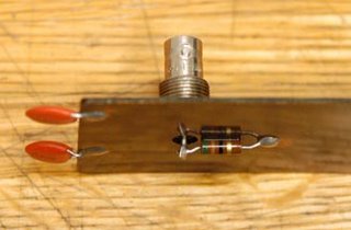
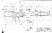
 I opened the X-ray anode 4 caps oil tank, and took the X-ray Anode trigger signal sampling circiut board(shown as right picture). This voltage monitor plate is different from what I imaged. This plate is placed near the high voltage cable, the cable radiation will induce a small voltage through capacitors. This induced signal is used to measure the x-ray anode pulse. The circuit drawing is revised correspondingly, please check this link. As a result, we don't worry about the voltage divider as we thought yesterday.
I pulled out the 4 caps and checked them separately, we did not find anything wrong. Then Mike suggested to measure the high voltage cable, so we disconnected the cable from the x-ray anode bar and applied 10 kV to the cable. The measured current was less than 0.1 mA, which means the cable is good. Up to now, we only left one item was not detected - X-ray anode bar. Thus we directly connected the anode bar without 4 caps. The measured current increased up to 1 mA as we slowly tuned the high voltage to 10 kV. We concluded that there must be a fixed resistance between anode bar and ground, the value was estimated by ~10M Ohms. As we kept increasing voltage to 20 kV, the current measured up to 1.5 mA, then droped a little bit. The current became unstable, swung between 1.2 mA and 1.5 mA. There may be two reasons to cause this phenomenon: 1) the flashover was occured on the surface of conical epoxy bushing; 2) discharging between aonde pipe and cathode bar because of the anode pipe bending .
No comments:
Post a Comment