Wednesday, April 26, 2006

Burks Oil Pump Overheating

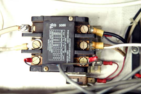
I found the red light was on when I turn on the oil pump switch. The power light was on when I pressed the reset button on the relay, however the motor did not run any more. The overload light was on after several seconds. After trying several times, I found the smoke from the motor, I think it's burnt:(.

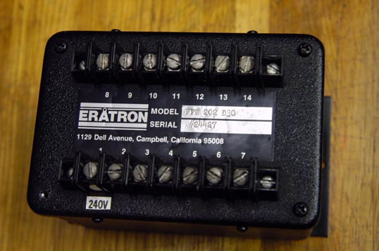
BURKS OIL PUMP OVERHAUL
TROUBLESHOOT
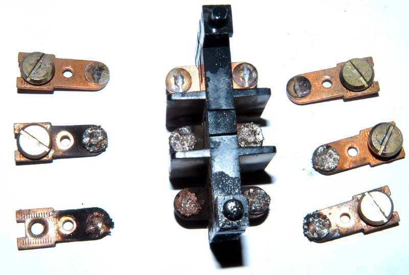
  • Overheating motor may have burnt out winding. 3 phase amps check will show unequal values on 3 lines.
  • Bad noises are probably motor bearing. Replace them immediately, or motor will be ruined.
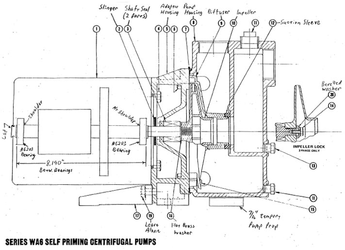
  • Oil pooling in the recess within the motor adaptor (item 5) indicates a worn shaft (ok if a new seal leaks for a very short time).
  • Special tools and parts are in the closet near rm 2159.
  • Standards tools: 3/8” ratchet with 9/16” + 7/16”sockets, and 12” extension. One large flat - blade screwdriver. 3/16” hex key.
GUTS OUT
  1. Electrical: Shut off motor switch. Label Switch, “LEAVE OFF”.
  2. Disconnect wiring.
  3. Drain: Close all oil manidold valves.
  4. Uncork 1/2 “Poly Flow plug at top of oil manifold, for air vent.
  5. Tap oil into clean beaker under pump drain valve.
  6. Transfer oil (If clean) to drip reservoir. Repeat until drained.
  7. Replace Poly Flow plug.
  8. Push “Pump Prop” disk (in special tools box) under pump housing.
  9. Unbolt pump body from motor / adaptor (bell housing): (4 bolts, item 6). Don’t loosen bolts that join motor to adaptor housing. Pull motor and adaptor housing away. Some oil will gush.
SHAFT SEAL OUT
Note: No left-hand threads are used on this entire pump.
  1. Located rubber doughnut “Suction sleeve” (Item 12) and remove it.
  2. Remove “Diffuser” (cone ? shaped, item 9); just 2 small screws.
  3. Remove O ring (Lab unit) or paper gasket (basement unit). If paper gasket is used, meticulously clean the sealing surfaces.
Impeller Removal:
  1. Clamp special big pinch clamp around bronze impeller, with the stud sticking through a housing hole.
  2. Unscrew impeller clamp bolt and brass beveled washer.Note: If screw is socket head, it has Loctite on threads. I tapped motor shaft with wrong (Course) thread, so it needs extra grip.
  3. Reapply Loctite when reassembling this motor.
  4. Pop snap cap off motor rear.
  5. With large screwdriver, remove impeller by “unscrewing” motor shaft.
  6. Catch impeller. Note flat brass washer behind impeller. Leave special pinch clamp on impeller, for reassembly.
Adaptor Housing Removal:
  1. Remove the 4 housing bolts, and pull off housing. You are fighting the drag of the rotary seal part that grips the shaft. If it’s really stuck, use special “motor bell puller”, with the CPI nut to protect the shaft threads.
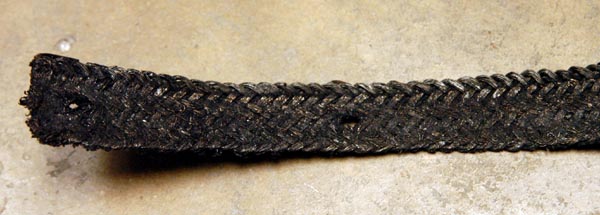
  2. Press stationary seal out of adaptor housing.Note rubber “slinger” washer on shaft. It needs replacing if it does not grip the shaft.
  3. Begin reassembly unless motor bearing need replacement.

MOTOR BEARING OUT
Motor Dismantle:
  1. Pull off slinger.
  2. Mark motor shell and ends for alignment, if not already.
  3. Unscrew 4 long screws from rear of motor.
  4. Pull front end off, with armature.
  5. Pull bearing: Note: It’s not necessary to remove front bearing (long shaft end), and protect shaft end from damage.
  6. Use shop puller to pull bearing off. Note: There may be a loose piece, a motor bearing clamp, laying loose behind bearing. Don’t forget to reinstall it.
  7. In like manner, remove rear bearing. Note: If damage to rear bearing is no concern, you may omit adaptor.
New motors don’t have the required internal threads in the motor shaft end, necessary to keep the impeller from spinning off. With the rear bearing remove, you can now chuck the armature shaft in the lathe, with the long end sticking out, and drill and tap for 1/4” -28 (fine) X 1/2" deep.

NEW BEARING IN

Note: Details of pressing techniques are not discussed here. One caution: Work with shaft only. Do not support or press armature body or fan.
  1. Clean long shaft of any rubber seal residue.Press bearing onto armature shaft short end, all the way to shoulder.
  2. Slip front bearing clamp (a piece of the motor), if used, onto long shaft end. Using “motor bearing installer”, press bearing onto armature shaft end, but stop when bearings measure an outside separation distance of 8.190”.
  3. Reassemble Motor as you took it apart. If long screws are stubborn, remove screws, sight through holes and give ends corrective rotational taps.
NEW SEAL IN

Note: It is reasonable to assume that a seal that has little wear and soft rubber parts should work fine if carefully dismantled, cleaned, silicone ? greased, and reassembled.
  1. Reinstall slinger washer, nominal 1/8” from motor face.
  2. Use steel wools and acetone to clean the seal recess in the adaptor housing.
  3. Press the stationary part of the seal into the adaptor housing, rubber lit first, using “stationary seal installer”, with the cardboard disk as a protector for the ceramic face. Even, straight, firm hand pressure is enough.
  4. Dab some silicone oil on the ceramic seal face.
  5. Grease motor shaft.
  6. Bolt adaptor housing onto motor.
  7. With the steady pressure, push spring ? loaded part of seal onto shaft, graphite first; don’t turn. Push all the way, only from the spring. As per disassembly, reinstall flat brass on shaft, then Impeller (snugly), special brass beveled washer, and shaft bolt (Loctite, only if ? - 20 threads).
  8. Remove impeller clamp tool.
  9. Replace motor rear snap cap.
  10. Reinstall diffuser.
  11. Grease and install new paper gasket or # 2- 263 O ring, as req.
  12. Reinstall suction sleeve on end of diffuser.
GUTS IN
  1. Bolt motor adaptor to pump housing, keeping flanges evenly gapped.
  2. Retrieve 7/16” pump prop.
  3. Reconnect wiring.
  4. Set valves for full oil flow.
  5. Waite 10 minutes for oil to flood the pump.
  6. Remove “LEAVE OFF” label.
  7. Turn on pump.

Tuesday, April 25, 2006

Redrawing the system timing schematics

I combined the front end laser and the Prometheus to run. I drew the timing schematics to understand the system control easily. Then I tried to synchronize the seed laser pulse and the Prometheus. I filled new gases into the Prometheus and ran it at 20kV. This time the Prometheus was trigger by the seed laser pulse. When I adjusted the time delay between the Railgap and the X-ray anode around 1.93 microseconds, I measured the maximum UV light. However, I could not synchronize the seed beam with the Prometheus very well. Another problem is the oil recycling system, the oil pump could notbe run, the light show it's overheat.

Eurotherm Firing Angle Control for Prometheus Operation

1. Introduction

Recently UIC purchased a Eurotherm 7100A SCR Controller to replace the no longer supported Eratron FPE 202-D30 SCR Controller. This Technical Note will discuss ways in which to utilize not only the Euroterm Controller but also any generic SCR controller for the charging of the main Thyratron Capacitor Banks. One goal of changing to a commercial controller is to eliminate much of the troublesome Firing Angle and PC Board Control cards that were utilized for the Eratron unit. The Eurotherm unit as ordered is a basic unit without “alarms” or “soft start” features that are useful in driving inductive loads like the HV Transformer. More advanced units incorporate a “safety ramp” that involves progressively increasing the Thyristor firing angle in order to apply the voltage (and current) to the load smoothly and thus reduce the start-up current of loads which either have a low resistance when cold or are inductive. For inductive loads, the “safety ramp” prepares the initial magnetization of the transformer to avoid saturating transformers on power up that can lead to large in rush currents to the primary. This note will show via simulations that it is relatively straightforward to control the present Eurotherm unit and incorporate “soft start” features.

2. Circuit Model Description
This circuit is essentially the same as that shown in the note “Firing Angle Control of SCRs during Charging”, 26 March 2006. The main addition to that circuit is the generation of the SCR control voltages (E1 and E2) by the Eurotherm unit, which is driven by a 0 to 5 Volt DC control signal. V1 is the 208 VAC rms line voltage and the “ideal” HV transformer has been modeled as having a 32kVAC rms output voltage (turns ratio of 154) with a secondary resistance, R5, of 2K ohms. R1 is the 0.1-ohm peak inrush current limiting resistor to protect the SCRs. The diodes are made up of three SCH20000 diodes in series and labeled as D1 thru D4. R3 is the series-charging resistor of 100K made up of ten; 10K 225-watt wire wound power resistors. The North and South capacitor banks are labeled as C1 and C2 and interconnected with a 3K resistor. R2 is the 70-ohm resistor for purposes of monitoring the pulsed charging current (Imon). The actual Pulse Modulator (PM) HV Schematic of Prometheus (see D-2151) shows a Transzorb 5KP6.0A that clips the Imon signal at a voltage ranging from 6.67 to 7.37 volts. This is done in order to accommodate the Pulse Integrator of the PM HV Control Board (see C-2154). This is not necessary for use of the Eurotherm unit and no feedback current via Imon is needed.

3. Results of Simulations

In the event of the SCRs becoming shorted or commanded to full on, the resistor charging string is the only limit to the charging current pulses and the time that it takes for the system to reach a full voltage of 32kVAC rms x 1.414 = 45 kVDC. The purpose of the PM Voltage Control Timing Circuit (see C-2155) is to limit the charging time available with the SCRs commanded to full on such that the Thyratron Bank Voltage as indicated by Emon never exceeds 30kV although the Anode rating of the CX1622 Thyratrons is 35kVDC. This time should include the “soft start” feature of about 8 full SCR firing cycles or 0.133 seconds. The results of a simulation showing the SCR Firing Angle (set at 180 deg), the Imon current pulses, the Emon charging voltage, and the first 0.2 seconds of the Transformer Primary Voltage, gives a maximum desired charge time of 0.820 seconds. The Top trace (Red) shows the Firing Angle ramping up to 180 degrees in 0.133 seconds with the corresponding Transformer Primary Voltage being given a “soft start” over 8 full cycles as shown in the Bottom trace (Black). The Imon current pulses are shown in the 2nd trace (Magenta) and charging resistor limited to 420ma with the Emon voltage of the 3rd trace (Blue) indicated at the complete charge of 30kV in 0.82 seconds.

If the SCRs or the Controller fails such that the SCRs stay on, then the only protection to stopping the charging cycle of the capacitor banks is to command open the AC Contactors that drive the input to the HV transformer. This means that if the Emon voltage continues to increase after 0.82 seconds, the contactors must open before 1.25 seconds, which is the time that the system will reach 35kVDC on the Anodes of the Thyratrons. Some sort of comparator circuitry for Vref and Emon would appear to be needed to actuate the opening of these HV transformer contactors. Although a version of this circuitry exists on schematic C-2154, there are simpler ways to implement this fault protection. One way that is already being used is that the Thyratron banks are being fired just after the time when the charge is complete.
Although it might seem complex to generate a ramp for the firing angle control, a simple pulsed RC circuit (time constant about 0.2 seconds) driven by the present Output Transistor of the PM Voltage Control Timing Circuit (see C-2155) could be utilized. The results are shown on the bottom four plots on the next page and can be compared to those at the top of the page for the linear ramp of the “soft start”. Note that any additional complexity in ramping the top of the firing angle voltage is not necessary since ALL SCRs and Diodes are being operated safely within their limits.
(Written by Randy)

Monday, April 24, 2006

Clipped Imon Signals

Randy sent an email talking about the I_mon Clipped signals.
=======================
I looked more carefully at the Schematic D-2151 and just noticed that the Transzorb is actually a 5KP6.0A which has a breakdown voltage between 6.67 and 7.37. The scope traces that you sent show the Imon peaks clipping at about 6.7 volts and so this all makes sense now. This explains to me why the current peaks have always looked near constant in amplitude and yet the Emon voltage charges exponentially. The "true" Imon pulses are probably decaying exponentially in time as I have calculated in previous models. This also means that the circuitry of schematic C-2154 is not driven by what the Imon current is really doing; the Imon pulses are acting more like an "enabling" gate. This circuit is not as smart with Imon feedback as I had thought but nevertheless I still need to understand what it does in more detail.
In summary, I am looking at this circuit (C-2154) more carefully to understand what it really does. I will also model and make some comments on what the Eurotherm Controller should do for a DC command input and how the system should charge versus various but constant phase angles (this is very simple to implement). In my mind, the ideal Firing Angle input should have a "soft start" ramp for about 8 AC cycles followed by an "average" Phase Angle that has an upward ramp to somewhat increase the area of the charging pulses and therefore enable the Thyratron Capacitor Bank to charge more near linear versus exponential. Although this process can be more efficient and quicker in time, the actual charging of the banks is of little consequence as long as no SCR or Diode ratings are exceeded. The ratings are safely limited by the 100k resistor charging string other than for the initial turn on that is governed by the magnetizing current of the transformer core.

Randy

Friday, April 21, 2006

Computer control SDG II

The SDG II can be controlled with a standard RS-232 serial port. I made a standard 9-pin D-sub male/female extension cable for hookup. Only three pins are used for serial communications:
PinFunction
2SDG II trnsmit data, computer receive data
3SDG receive data, computer transmit data
5Gound

Through the serial communication, I can control the Hurricane laser repetition rate acuurately. By sending command "set:rate 0127", the rate was fixed at 507Hz/127=3.99Hz.

Thursday, April 20, 2006

Synchronizing the seed pulse

Previously we used the pulse generator to trigger the Prometheus, actually the trigger pulse should be generated from the front end excimer laser system. So I tried to send the laser pulse to trigger the Prometheus today. I set the laser repetition rate at around 4 Hz, then it was divided by 10 times, this 0.4 Hz pulse was the main pulse to trigger the Prometheus. I used a photodiode to measure the front end laser pulse. There was a jitter about ~4 microseconds between the Thyratron trigger and the laser pulse.

Tuesday, April 18, 2006

Timing for whole system

It's very import to synchronize the seed laser pulse with the Prometheus. In our old system, a 10 ms delay time has been added before the seed pulse was sent to Promtheus, which made it very easy to trigger the gas nozzle when the laser beam reached. However, in the new system it's only about 2 microseconds was given. We had to trigger the nozzle using the former laser pulse, which made the nozzle time delay more than 2.5 seconds when the system were run at 0.4Hz. I changed the system timing shown as the right diagram. The Prometheus will be fired when the next seed laser pulse comes, which will give the later equipment enough time(~250ms @ 0.4Hz) to be adjusted. I think this is better than 2.5 seconds time delay.

Monday, April 17, 2006

Moving the time delay forward

I measured the voltage and current of H.V. transformer when I changed the time delay. Here is the scope traces when the delay changed from 1280ms to 1580 ms @ 10 kV. Please note the current wave form @ delay less than 1480 ms, there was a current later than the charging current.

There were no miss fire when I set the delay time less than 1480 ms when I increased the high voltage up to 20 kV. After I fix the Prometheus timing, I will try to send the seed beam and adjust the time to synchronize them.

Friday, April 14, 2006

Calibrating the charging voltage

We calibated the charging voltage at increments of 10kV, 15kV, 20kV and 25kV using a Fluke high-voltage probe connected to the Thyratron capacitor bank and read with a Fluke digital meter. The results of these measurements indicated that the system charged to about 19kV when the control panle meter actually readout a voltage 0f 24.5kV. This error is merely caused by an error in the high voltage divider at the output of the transformer that needs to be fixed. Unfortunately, this also meant that the maximum voltge that the system could be charged to was 19kV.

During these measurement, it was noticed that erratic charging occured at the higher voltages above 15kV and, in fact, the sytem operated correctly only every other pulse. The pulse rate was then slowed down to one pulse every 5 seconds. Although the initial timing adjustment seemed logical and worked up to 15kV, further insight from the above trace indicated that it is desirable that there be a longer recovery period after thyratron firing before commanding the system to charge. The Thyratron should recover very rapidly (less than 1ms)but the induced transient noise in the system may need a much longer recovery period in order for the present firing angle electronics to work properly. This can be seen in the slight negative signal right after Thyratron firing and to last about 0.2 seconds. Rather than increasing the Charging Delay to about 2.5 seconds as had been done, the delay should have been reduced to about 0.8 seconds. This would have resulted in a charging delay of 0.8 seconds, a charge time of 0.9 seconds, and a charge hold time of 0.8 seconds for a total cycle time of 2.5 seconds. As mentioned previously, the system was finally run at 0.4Hz at 15kV for about one hour with no adverse heating of the charging resistors being noticed. Although the evidence presented somewhat confirms that timing has been the main problem during the past 4 months, only operation at higher voltages and longer periods of time can guarantee that the charging resistor problem is “really” fixed. (from Randy's report)

The below is the experimental data.
DIAL
H.V.
Probe(kV)
Control Panel
Meter (kV)
C-2153
J1 (V)
6.1611.1014.03.35
7.1013.0016.53.91
8.7215.2519.64.6
10.0019.0024.55.7

Randy put a Rogowski coil to measure the current pass from the Thyratron to ground. When we carefully adjusted the time delay bewteen the rail gap and the Thyratron firing, we certainly found the current closed to 0. This result totally matched Randy's simulation.

Thursday, April 13, 2006

Adjusting the time delay 2498 ms

After review of the timing diagram (shown as the left schematics), we decided to adjust the time delay between the firing angle and the thyratron firing.

The scope traces are shown below. The lower trace shows that the charging current pulses are nearly constant in amplitude. This does not lead to constant power charging of the capacitors as evidenced by the exponential rise of the voltage in the middle trace. This exponential rise is further aggravated by the fact that the firing angle of the top trace is decaying in time whereas it should be probably be increasing in time.

Wednesday, April 12, 2006

Invesigating the main charging system

We put the good Eratron SCR controller connected to H.V. transformer, then we set the charing voltage 10 kV to measure the charing voltage and transformer secondary current. It was shown in the right picture, these wave forms are similar to the scope traces recorded on 9 March, 2006. Note the second step in the firing angle indicating that the charging cycle has been disrupted by the Thyratron firing too soon. It was hypothesized that the extra current drawn before and during the Thyratron firing caused the 10K resistors of the charing string to overheat.

Assuming the repitation rate is 0.4 Hz, the Stanford Box will send a trigger pulse per 2.5 second. According the old timing setup, the firing angle should be sent after 2.1531 seconds. From the left timing diagram, the Thyratron was triggered during the capacitors were charging. The time delay between firign angle and thyratron firing was around 347 ms, which matched the scope traces. The timing must be adjusted to move the charging time backward or forward such that the charging cycle started after or before the thyratron firing.

Tuesday, April 11, 2006

Removing ERATRON from X-ray Anode control system

By analyzing the x-ray anode trigger circuit, we concluded that we can remove the ERATRON and SCR power block from control unit and drive the system directly with Hiptronics H.V. power supply. As shown in the right picture, we removed the SCR and connected 208 VAC directly with step-down 240/120 autotransformer to drive Hiptronics 30 kV/5 mA power supply. All but the voltage meter were removed from the X-ray anode PCB, the remainder of the board served no function.

In the beginning, we could not drive the Hiptronics to 30 kV, the output was only 15 kV. However, the output could reach 30 kV when we energized it with regular 120 VAC power. So we tried to exchange 208 VAC phases, the Hiptronics ran normally after phase exchanging. I could detect the x-ray flux.

The RC charge time of the Hipotronics power supply is dominated by the 2.5M series charging resistor and the three 0.1uF capacitors in parallel (total value of 0.3uF), which are located in the X-ray Anode oil tank. The calculated time constant is 0.75 seconds. Since the system has a cycle time between pulses of 2.5 seconds, this means that the Hiportronics will charge to about 95% of the set value. It was found that good x-rays were generated for a set voltage of about 25kV (this also corresponded to a meter reading on the main system control panel of about 150kV). A setting of 20kV was too low and no x-rays external to the machine were measurable. (by Randy Carlson)

Randy measured the Primary resistance of H.V. transformer by measuring the current of a DC voltage around the transformer. The value is about 30 miliOhm. Unfortunately we were not successful in measuring the inductance with General Radio Bridge.

Monday, April 10, 2006

Installing the New Grounding System

Randy and John came to help for maintaining the Prometheus. They brought the scanned and clean schematics of the system.

We also changed the old system, this time the ground is connected by the copper sheet, which will provide a good grouding for the Prometheus. Randy and I discussed to try running the X-ray anode without the SCR controller, which would simplify the control system, we will test it tomorrow.

Friday, April 07, 2006

Time of Flight Mass Spectrometer

We already installed TOF. The right picture shows the grids and the shell. The below is the schematic of TOF in our lab. We planned to put another MCP on the right side to measure electrons or ions. The disk shows the connector for TOF.

Wednesday, March 29, 2006

Ordering EUROTHERM 7100A SCR controller

We found a SCR Power controller similar to our SCR controller. The product is from EUROTHERM.

The Model 7100A is a new range of economic SCR Power Controllers for use with resistive, infrared or inductive loads. This unit features integral heatsinks with analog voltage or current inputs for precise control.

Our ordering code is 7100A/100A/240V/230V/XXXX/MSFU/PA/XXXX/0V5/ENG/NONE

Monday, March 27, 2006

Transformer for X-ray Gun H.V. Power Supply burnt

Mike replaced the IC chips and transistors already, then we send a control signal pulse to measure the SCR output. The waveforms looked well, so I install the SCR controller in the X-ray Anode control box.

We tested the whole system in the afternoon, unfortunately the x-ray gun could not be run correctly. The x-ray anode high voltage was not monitored, while the high voltage connected to the Thyratrons was pretty good. After running a few minutes, I smelled the smoke. Then I found the transform connected between SCR and X-ray anode H.V. power supply was burnt.
===========================
AUTOTRANSFORMER P-8634
Primary ---- Line Cord
230V 50-60Hz

Secondary ---- Receptacle
115V@400VA

STANCOR Chicago, IL

Friday, March 24, 2006

Data acquiring system

We received the Tek 2024 scopes this afternoon, John helped me to install them in the rack. I connected these 2 scopes and TDS 520 to the computer with GPIB cables. The data can be acquired in real time, even it's not as fast as the scope response. I think it should be enough to obtain the data at 0.4 Hz. Actually we don't need to acquire the data for every shoot, we only need some special data for diagnostics. Previously Keith only used two channels scope to track the signals, which could provide enough information. Now we are using 10 channels to measure the signals.

ERATRON FPE 202 D30 Circuit board

Mike already removed all IC chips and put the sockets for pluging easily. He wants to replace all the IC chips from IC1 to IC8 and transistors Q1 to Q3. Until now we received the chips except IC4 and IC5.

No.Chip/TransistorFunction
IC1TL084CNLow Noise JFET Quad OpAmp
IC2CD4093BE14-Dip Quad 2In Schmit Trgr
IC3LM741CNOperational Amplifier
IC4MC14027BDual JK Flip-Flop
IC5CD4046BECMOS Micropower Phase-Locked Loop
IC6TC084CNLow Noise JFET Quad OpAmp
IC7LM555CNTimer
IC8CD4082BECMOS Dual 4-input AND gate
Q1J113N-Channel Switch
Q2MPS A13NPN Darlington Transistor
Q3MPS A13NPN Darlington Transistor

Thursday, March 23, 2006

Changing the Beam Stabilization Setup

It's difficult to recover the beam stablization setup if we move it, so I changed the setup. Kevin helped to make the plate and the posts. I aligned the beam into the beam expander and make sure the expand beam finally enter the target chamber correctly. This time we only used one mirror to steer the beam to the CCD camera, I will test the imaging system soon.

Monday, March 20, 2006

Repairing the SCR controller

Mike contacted PLC Center requesting the circiut drawing of SCR controller, unfortunately the company did not have any drawing. Like Mike doing, they only can replace the chips one by one to test the logical output. Up to now, Mike already ordered the chips and transistors for the circuit repairing.

Friday, March 17, 2006

beam stabilization system

Regarding the installation of the LLG beam stabilization system at UIC it can be
stated that
1. The optimizations works properly.
2. The closed loop control works in a standard configuration i.e. beam control is achieved with a stationary 500 or 4 Hz pulse train respectively.

However, some problems encountered during the installation schedule have to be solved:
1. The motherboard of the PC delivered by LLG is defect.
The fastest solution, we suggest is that you buy a identical mainboard and replace the old one on your own. Regarding the compensation of your financial effort, we should discuss with Klaus Mann and Uwe Wachsmuth next week.
2. The contrast ratio of the pre-amplified pulses and the frontend ones are approximately one to two orders of magnitude too high. Thus, at an attenuation level sufficient to perform the closed loop control of the frontend beam,the CCD chip gets damaged after illumination with very few (app. 10) amplified pulses.
Actually the chip shows 7 damaged pixel, but this virtually does not hit the performance,as we use only a 1/16 part of the chip, so a non damaged part can be selected.
The best solution we think would be the use of a variable attenuator, based on a mechanical shutter. This shutter should have a contrast ratio of 100, and could easily be triggered by the 4Hz Trigger of the TWIN amplifier without any software support. This could be done in Goettingen, but doing it by yourself in Chicago will be much faster.
3. The closed loop control based on switching the frondend from a 4Hz to a 500Hz mode for a short time interval between two consecutive 4Hz TWIN pulses does not work. Part of this failure seems to be the high overexposure mentioned above. Another reason is probably some internal logical software bug. - However, the mode switching works, and closed loop control has been achieved without amplifier, although the software fails to set the correct values the the pulse timing schedule.

This problem should be solved in Goettingen during the next weeks. An updated version of the program may then be tested by Dr Song, who will have my full support via email or phone.

(Reported by Bernd Schaefer)

Tuesday, March 14, 2006

Testing computer control system

We connected SDG-II to computer with RS-232 port.

Monday, March 13, 2006

Installing laser beam stabilization equipment

Dr. Bernd Schaefer came to help us install the equipment of laser beam stabilization today. I will assist him. I ran the TWIN excimer amplifier, its output energy reached ~30 mJ. By sending less than 1% transparent beam behind a reflected mirror to the equipment, we could monitor the laser beam profile. The problem is after the same ND filter the transparent of seed beam is too weak compared to the pre-amplfied beam.

The computer was sent from Germany, we could drive it by 115V power supply. I ordered a 110V 500W power supply for computer.

Thursday, March 09, 2006

Exchanged SCR Phase Controller

Because the X-ray anode preionizer system used the same high voltage control design as thyratron discharging. We exchanged the SCR phase controller ERATRON FPE 202 D30 for troubleshooting.

This time, I can control the H.V. pulse for thyratrons, but cannot control the x-ray anode H.V. pulse. We confirmed that SCR controller cannot be run well. When the H.V. pulse modulator set scroll was tuned from 3.0 to 6.0, the current waveform at transformer primary was followed to change. The voltage meter showed the H.V. changed from 5 kV to 15 kV.

I also monitored the transformer secondary current I_mon and SCR firing angle. We finally concluded that SCR firing phase controller was not well, Mike helped to replace some problematic chips. ERATRON has been not existed, it's impossible to buy the same controller. The similar controller may be found to replace. A company named PLC Center provide repairing service. We would like to send this block to them for repairing if we cannot do it.

Wednesday, March 08, 2006

Failure of H.V. pulse control

Like before, we failed to control the high voltage output. When I turned on the H.V., even without the modulating pulse (it means no firing angle signle applied to SCRF-1), we could measure the high current through the transformer primary. So I disconnect the primary of big transformer and connected them to a step down (40:1) small transformer. Then we measured the wave form from the secondary. We always saw the wave form (see the picture) which could not be adjusted.

Tuesday, March 07, 2006

SCRF-1 pin 12

We received the 451L chip this morning. Then we installed it on circiut board. The right picture shows the firing angle wave forms with/without H.V. pulse modulation. When I tuned the voltage amplitude, the firing angle voltage was followed to change.

Unfortunately, there was not any output yet. I checked the wires and found pin 12 on SCRF-1 was losing. Maybe this caused no high voltage.

Friday, March 03, 2006

Frequency voltage converter AD 451L

Today we combined the C-2154 circuit board and SCR together to check, we found pin 13 at C-2154 was not connected to common point. This caused the output of firing angle floating. After we fixed it, the firing angle pulse was changed. The test result was shown on the right picture, the wave 1 is the pulse without out common, wave 2 is the pulse after fixing.

Then I installed C-2154 and SCR back into the system for testing, unfortunately the high voltage could not be measured yet. The difference is that there was no high voltage output even after running for a couple of minutes. So we wanted to remove the C-2154 card to check again, however, we accidentally took off the card with the power on. We found the power was still on even I turn off the switch. Then we found the frequency-voltage converter AD-451L does not work, it must have been damaged when we removed the circuit board. I already ordered 451L from Newark. We will change the chip and fix the switch next Monday.

Thursday, March 02, 2006

Check SCRF-1 and SCR independently

I removed SCR Firing Circuit SCRF-1 (ERATRON FPE 202 D30) and SCR (Powerex CM431290) from M03 board. Mike connected them (circuit shwon as yesterday) to check them independently. The firing angle input was a pulse with amplitude of 0~5 V and duration of 140 ms, pin 7 of SCRF-1 connected to ground. An 1:4 step down transform was connected to SCR out port. When we tuned the firing angle amplitude, we measured the transform secondary wave form. Actually we have not found anything wrong of these measured parts, the output could be adjusted by tuning the firing angle amplitude. We will send pulses generated by C-2154 board to SCRF-1 for checking the output tomorrow.

I also filled the new gases into the LLG-TWIN excimer and ran the front end system.

Wednesday, March 01, 2006

SCR gate 2 and gate 1

We firstly disconnected the transform primary to measure the SCR gates G1 and G2. The picture of wave forms is shown below. During measurement we found the firing angle was changed from pulse to continued voltage. I thought this might be caused by the feedback.

In order to send a correct control pulse to SCR controller, we sent a pulse generated by the function generator. This time we connected the transform primary, the waveform was shown as left bel. We found only SCR gate 2 pulse was modified, the gate 1 was not changed anymore.

Tuesday, February 28, 2006

Changed Relay K4 and SCR on M03

I received the SCR and relay this morning, I installed them and test the system again. However, the high voltage still could not be controlled. Mike helped to check the circuit board again.

Craig loaned us the used computer (400 MHz, Pentium II, better than our old one), which can be used to grab the wave froms from the oscilloscopes. I installed Tektronix WaveStar and successflully obtained the wave forms, much faster than the old machine.

Friday, February 24, 2006

Relay P40C42A12D1

According to the yesterday's current and voltage measurement, we concluded that there must be a position broken to block the current flow through transform primary. The most possible is the relay K4 on R03 board. So I removed the relay to check.

The relay K4 module is P40C42A12D1-120. I found the pins were burnt due to the high current. One pole was almost melted together, and could not be detached. This broken relay effected the SCR normal operation, might cause SCR breakdown. I have not found the relay from Newark, they suggested to replace it with TYCO 1423254-6. However there was no in stock, we have to order at least 9 pieces if we really want to buy. So I ordered the similar module -- P40P42A12P1-120. Although it's not the same relay, we can replace the old pins with new ones. I think it's the fast way to fix the problem.

Thursday, February 23, 2006

Measuring the current

Before we receive the ordered SCR, I found an old SCR in the lab (don't know it's good or not). I installed it and tried to measure. Unfortunately, this SCR was bad, I could not monitor the current even I could measure the input voltage. I used the current clamp to measure the current on the X-ray gun high voltage power supply, I obtained the current waveform. The high voltage power supply for x-ray gun was designed using the similar design of M03.

Tuesday, February 21, 2006

SCR CM341290

I contiuned to test the SCR part today. When I turned on the system, I could measure the firing angle signal from C-2154 board. But I have not measured the high voltage. After warming up several minutes, even I did not send the firing angle signal, I could monitor the high voltage. This phenomenon might be caused by the bad SCR?

I found an interesting paper about the inverse parallel thyristor written by Dr. Henry E. Payne.


Figure. 1

Fig.1 illustrates a typical installation of a 50A single-phase thyristor unit phase-angle controlling a 480ac voltage to the input of a transformer with a low-voltage resistive heater connected to the transformer secondary.

Note the resistance value: RL. All properly designed thyristor controls will have certain minimum resistance loads that they are able to control, if, for no other reason, because this minimum resistance must be large enough to limit the current through each thyristor to its rating when it switches into the ON state. From OHM's Law this value is, typically, the RMS mains voltage divided by the maximum nameplate current rating of the power control.

And for a direct-connected resistance heater, this would be a correct value.

HOWEVER, some might also assume that this is the same value when connecting an SCR power control to a transformer. IT IS NOT. All transformer primaries will have a DC resistance value much lower than the primary voltage divided by the primary current rating. As a result the maximum current that can flow through the loop 1-4-3-2 is limited only by RL and whatever system impedance is available at terminals 1 and 2. If F1 is selected properly to protect the two SCRs and there is no consideration given to the transformer RL, it is very likely that one will have nuisance fuse blowing during normal operation of the system due to the transformer magnetizing current inrush.

When SCRs are either in the OFF state or in operation, one cannot assume that they will not misfire due to some line transient. After all, that is the reason that all properly-designed SCR controls will always have an RC network connected across the SCRs as shown in Fig.1. The RC network and the dv/dt rating of the SCR combine to prevent over 90% of the line noise from causing a misfire. Nonetheless, there is always a bigger transient on the mains, and every solid-state power control must be designed to allow for that inevitability. By over-sizing the SCR/fuse combination for transformer or other high-inrush loads, one can assure oneself that nuisance fuse blowing is unlikely to occur, nor will there be any fatigue damage to the fragile, silicon SCR pellet.

Finally, one must also ensure that phase-angle control --see Fig.2-- of the transformer primary always impresses a symmetrical ac voltage on the primary with no significant dc component. The latter can cause saturation of the transformer core, which will lead to excessive current and temperatures which cannot be tolerated for long-term operation. Transformers and other inductive loads require full-cycle gating of the SCRs to ensure that the SCRs will remain in the ON state, regardless of the inductive load characteristic (where the load current may lag the SCR voltage by 90 degrees or more).


Figure. 2

http://www.payneng.com/AN11-18/AN11-18.htm
Thyristor Theory and Design Considerations(PDF)

Monday, February 20, 2006

ERATRON FPE 202 D30

We removed the SCR control unit -- ERATRON FPE 202 D30 to check. We could not find anything wrong of this part.

The SCR is Powerex CM341290 (Voltage 1.2 kV, Current rating: 90 A). I measured the firing angle and high voltage current.

Friday, February 17, 2006

SCR control unit

Mike helped to fix the C-2154 board, we measured the firing angle signal independently and found it very well. However, the high voltage could not be controlled. Even the firing angle signal has not been sent to the SCR control unit, there was a high voltage output. We could measure the current as soon as switched on the high voltage without the firing angle. This caused the whole system breakdown, we must check the SCR and its control unit next Monday.

Wednesday, February 15, 2006

Keep checking C 2154 Board

I replaced the broken relay K1 on R03 module as soon as I got the ordered relay. But I did not monitor the high voltage. We could not detect the firing angle signal from C-2154 board. Mike checked the board again and found pin 7 of A4 mechanically broken. After we replaced the A4 chip, we tried to run the system. This time, we could measure the firing angle, but the high voltage monitor still showed zero. We disconnected the firing angle output on C-2154 board and sent a pulse wiht 3 V, 500 ms to the SCR control unit, then we could see the high voltage monitor worked well. It means the SCR and control unit is okay. So we will continue checking the C-2154 board.

Tuesday, February 14, 2006

High Voltage Control Module R03

I checked the R03, measured the signal of pulse modulation H.V. reference voltage (frequency). I have not found anything wrong. The frequency can be tuned from 0 to 10 kHz, which will be converted to voltage 0 to 10 V DC by chip L451 on the C-2154 board. Now we are afraid the feedback or SCR control unit may cause the high current. Mike suggested to send a 800 ms square pulse generated by function generator to test the SCR control unit. If the system running well, we can confirm it's feedback to effect the current. Unfortunately when I installed the circuit board in R03, one leg of the relay K1 accidently was broken. The relay model is Potter & Brumfield R10-E1P4-115V, I have ordered it from OnlineComponents.

Friday, February 10, 2006

C-2154 PCB repaired

We checked the Pulse modulation PC Board and replaced the Zener diode D9 and capacitor C1. Then I put back the board to test the system, unfortunately the system could not run in the right condition. I could not adjust the high voltage yet. When I monitored the frequency input Vref, I found there was only a noise signal. The reason of this may be the extend board or the signal from Control Rack R03.

Thursday, February 09, 2006

Pulse Modulation Control PCB

I already replaced the SCR on high voltage power supply board M03, also checked the high voltage diode rectifier SCH20000 yesterday. But I could not tune the voltage later, I found there was not correct output at the Firing Angle at pulse modulation control PCB. That trigger pulse voltage was less than 1 V.

Mike helped me to check the board. We measured the pulses on pin 1 at A4, pin 7 at A4, pin 6 at A1 and pin 6 at A2. We found it's feedback to decrease the voltage of Q1 input.

Tuesday, February 07, 2006

10K Ohm resistors burned again

It's weird that the 10K Ohm resistors were burned again. This time were second resistor and third one. The current must be drained too much somewhere, so that the resistors were burned again and again. We measured the current which passed through the whole system, here we named it Imon. Now Imon only can keep about 300 milliseconds. I also measured the firing angle from Box 2270, that waveform looks strange, too.

I found some waveforms which were recorded on Jan 10th, 1995. The current should be kept about 800 milliseconds, and the firing angle looked like a flat pulse. From those pictures, there was one waveform mostly like the above one, it marked "Drawing high current". There was another note on the other waveform, "Swayback should not be here. Indicate I separate changing cycles due to only 1/2 of the SCR firing block working".

We already checked the 2155 circuit board in the box today, it's very good. We will check the 2154 board, which generate the firing angle signal.

Monday, February 06, 2006

Unltra-high Intensity Ti:Sapphire/KrF* Excimer Hybrid Laser System

1. Introduction

Based on the chirped pulse amplification (CPA) technique [1] and the Kerr-lens mode-locked Ti:sapphire laser [2], a laser intensity of 7x10²⁰ W/cm2 has been achieved by the solid state laser system. In order to reach this intensity, a laser system with extremely high peak power of 1500 TW (440 fs, 660J at 1054nm) [3] is required, which leads the system very complicated and expensive. Since the laser intensity is inversely proportional to the square of the wavelength, the given high intensity can be reached using the ultraviolet (UV) laser with much lower peak power. The main method to produce laser pulses in the UV spectral region is using rare gas-halide excimers. Unlike in solid state laser, excimer lasers with appropriate heat exchange can avoid thermal effects such as thermal lens; also due to the less optical distortion in the gas medium, the excimer laser has an advantage to give better beam focusability. By combining compact femtosecond laser with KrF* excimer laser chain for amplification of the converted UV pulses, our old Ti:Sapphire/KrF* excimer hybrid laser system [4] is upgraded. The new system can produce the laser pulse with a peak power of 4 TW and focused intensity up to 2 x10²⁰ W/cm2.

2. System configuration

The Ti:sapphire/KrF* laser system is composed of the front end and the large aperture KrF* excimer laser amplifier.

The front end consisted of three main parts (Fig. 1). The first part is a commercial Ti:sapphire solid-state laser system (Spectra-Physics Lasers Inc., CA), which generated a 100-fs pulse train at 745 nm with a repetition rate up to 500 Hz. The output pulse energy is around 600 mJ. The second part is using the polished BBO crystals with 0.8 mm and 0.24 mm thickness for frequency doubling and tripling respectively. A 1.1 mm thickness MgF2 wave plate is inserted between the crystals to compensate the group velocity delay after frequency doubling. The output energy from the tripler is about 120 mJ with ~100 fs at 248 nm, which is sent the third part to seed the excimer preamplifier. The excimer module is arranged in 4-pass off-axis geometry in order to reach the optimal conditions for amplifying femtosecond pulses [5]. The output from the first double-pass excimer amplifier is spatially filtered by a 150-mm-diameter pinhole in a diffraction-limited manner in the vacuum pipe. A pair of grating is placed after the first 2-pass amplifier to compensate the dispersion before propagating through the amplifier chain by adding a negative pre-chirp to the laser pulse. The output of the pre-amplifier is up to 20 mJ with ~120 fs pulse duration.

After the pre-amplification the 248 nm pulse is collimated and expanded to a 10-cm diameter beam using a 4-power reflecting telescope of Dall-Kirkham design. The final seed pulse is injected into a large aperture KrF* excimer amplifier [6]. This powerful amplifier is designed to operate at relatively low pressure and low gain in order to reduce wave-front distortion and amplified spontaneous emission (ASE). The final pulses exhibit the average energy of 600 mJ at repetition rate of 0.4 Hz. A portion of final laser pulse is sent to the frequency resolved optical gating (FROG) device for the measurements of pulse duration and phase shift. The pulse duration is ~200 fs, and the phase shift is around several mrad.

2. Focusability

In order to calculate the laser intensity at best focus, the focusability of the seed pulse after it passed through the large aperture excimer amplifier was measured. The 10-cm-diameter seed beam was sufficiently attenuated so that no air breakdown or the beam self-focusing occurred. The beam was directed onto an off-axis parabolic mirror of 20 cm focal length. The focal spot of this f/2 optical system is imaged by a 40 times UV microscope objective (Partec GmbH) onto a CCD camera (Watec-502B) without the cover window.

The beam profile at the image plane of the microscope objective is shown in Fig. 2. The focal spot size of the 248-nm seed pulse is ~1.5 mm in diameter, which is about a factor of 1.5 times larger than the diffraction-limited spot size.

3. Conclusion

This upgraded system finally generates 200-fs pulse duration, the 1.5-mm-diameter focal spot size, and the laser energy of 600 mJ, which gives an average intensity of ~2?1020 W/cm2. To our knowledge, this system generates the highest laser intensity at 248 nm. We will use this laser to develop high brightness hard X-ray source from a Xe cluster target for application in biological microimaging [7].

References

[1] P. Maine, D. Strickland, P. Bado, M. Pessot, and G. Mourou, “Generation of ultrahigh peak power pulses by chirped pulse amplification,” IEEE J. Quantum Electron. QE-24, 398-403 (1988).
[2] D. Spence, P. Kean, and
W. Sibbett, “60-fsec pulse generation from a self-mode-locked Ti:sapphire laser”, Opt. Lett. 16, 42-44 (1991).
[3] M. D. Perry, D. Pennington, B. C. Stuart, G. Tietbohl, J. A. Britten, C. Brown, S. Herman, B. Golick, M. Kartz, J. Miller, H. T. Powell, M. Vergino, and V. Yanovsky, “Petawatt laser pulses”, Opt. Lett. 24, 160-162 (1999).
[4] F. G. Omenetto, K. Boyer, J. W. Longworth, A. McPherson, T. Nelson, P. Noel, W. A. Schroeder, C. K. Rhodes, S. Szatmar, and G. Marowsky, “High-brightness terawatt KrF* (248 nm) systgm”, Appl. Phy. B 64, 643-646 (1997).
[5] G. Almasi, and
S. Szatmari, “Optimization of multiple-pass off-axis KrF amplifiers”, Appl. Phys. B 60, 565 (1995).
[6] T. S. Luk, A. McPherson, G. Gibson, K. Boyer, and C. K. Rhodes, “Ultrahigh-intensity KrF laser system”, Opt. Lett. 14, 1113-1115 (1989).
[7] A. B. Borisov, X. Song, F. Frigeni, K. Boyer, and C. K. Rhodes, “Ultrabright Multikilovolt Coherent X-Ray Source at ~2.71-2.93 ?”, J. Phys. B 36, 3433-3455 (2003).

Friday, February 03, 2006

Systerm testing

After changing the thyratron on the south side, we tried to run the system today. I ran the system under 15 kV, it still ran well after one and half hour. No any click sounds occurred from the south side bank, even that changed thyratron looked a little bit different from the others.

Thursday, February 02, 2006

Changed south side thyratron CX1622

We concentrated on the south side trigger today. We found one of the thyratrons on the south side was triggered unstably. Inside that thyratron, the small arcing was observed during the period between two trigger signals. Mike suggested to replace that one immediately. When I lifted the thyratron board, I am surprised to find the conduct tape was so dirty.

This conduct tape connected the thyratron board to the ground, that's why the sparks on the plate were always obtained. So we removed the old dirty conduct tape and put a brand new copper tape.

Because we don't have new thyratron CX1622 at hand, I installed a used one which was probably still good.

Wednesday, February 01, 2006

Keep Passivation

I continue to passivate the Prometheus, except south side sometimes missing fires, upon to now
everything sounds very well. Now I am tracking the south side transformer primary, secondary,
filament 1st stage and 2nd stage, I hope to solve this random trigger problem soon.