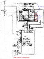
 We firstly disconnected the transform primary to measure the SCR gates G1 and G2. The picture of wave forms is shown below. During measurement we found the firing angle was changed from pulse to continued voltage.
  I thought this might be caused by the feedback.
In order to send a correct control pulse to SCR controller, we sent a pulse generated by the function generator. This time we connected the transform primary, the waveform was shown as
 left bel. We found only SCR gate 2 pulse was modified, the gate 1 was not changed anymore.
1 comment:
Constant current charging of the Thyratron Capacitor Banks requires that the phase angle of the two SCRs increase in time for each charging sequence. This is required in order to linearly increase the transformer output voltage as the capacitor voltage increases linearly in time. A possible SCR failure mechanism is that the SCR controller circuity sets the phase angle of the SCRs for a fixed charging voltage and does not vary the phase angle in time. This mode of operation results in RC type charging which can make the system "appear" to be operating normally except for the eventual failure of the charging resistors as has been seen several times in the past few months.
In a RC charging scheme it can be shown that the charging resistor dissipates the same energy as that delivered to the capacitors being charged. Such a charging system is only 50% efficient and is independent of the value of the charging resistor string. Experimentally the exact charging characteristics of Prometheus could be monitored by sensing the current
in the ground leg of the transformer output. The measured current will either be the desired constant current or for RC type charging it will be a decaying exponential. Depending upon the nature of the SCR control circuity, the measured current may be intermediate to these to extremes.
Let's assume for fault analysis purposes that the system is somehow being charged in pseudo RC fashion and that the Thyratrons are always fully recovered and working perfectly. The energy to be stored in both thyratron banks is E = 1/2CVV = 1/2(3uf)30kV x 30kV = 1350 joules. This is also the amount of energy that is dissipated in the resistor string during each charging cycle. The average power dissipated in the string at a repetition rate of 0.4 Hz would be P = 1350 x 1/0.4 = 3375 watts. The resistor string has a power rating of 10 x 225 = 2250 watts. Under these conditions without detailed diagnostics, the Prometheus charging system would seem to be working correctly but the resistors would eventually fail due to excessive power just as has been observed.
As mentioned previously, a separate resistor charging string for each thyratron bank would cut the power in half for a RC type charging fault. In this fault case each resistor string would dissipate 3375/2 = 1688 watts which is under the power rating of 2250 watts. It is interesting to note that if these two strings had been in existence, one may have thought that everything was working fine with Prometheus as stated not to long ago in the blog. It's only the physical failure of the resistor charging string that has led to investigation of problems with the SCRs and controller circuity.
In summary, the more likely failure of the resistor charging string is due to the SCRs and controller circuitry operating in a pseudo RC type charging mode rather than the desired constant current mode. It would be relatively easy to add another 100K charging string to the output of the transformer and thus provide some of the advantages of isolation for the charging of the two thyratron banks as stated in a previous E-mail. In either case, this present failure associated with improper operation of the SCRs shows how faults can be "masked" and the necessity for on line dedicated diagnostics.
Randy
PS -- from your statement about the 400 MHz Pentium computer on the blog, it is clear that any dedicated diagnostics system will need to include a new and much faster computer which is can be had these days for $1 to $2K or so.
Post a Comment