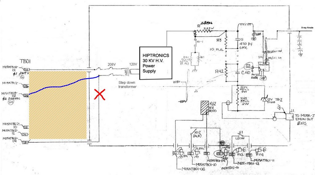
 By analyzing the x-ray anode trigger circuit, we concluded that we can remove the ERATRON and SCR power block from control unit and drive the system directly with Hiptronics H.V. power supply. As shown in the right picture, we removed the SCR and connected 208 VAC directly with step-down 240/120 autotransformer to drive Hiptronics 30 kV/5 mA power supply. All but the voltage meter were removed from the X-ray anode PCB, the remainder of the board served no function.
In the beginning, we could not drive the Hiptronics to 30 kV, the output was only 15 kV. However, the output could reach 30 kV when we energized it with regular 120 VAC power. So we tried to exchange 208 VAC phases, the Hiptronics ran normally after phase exchanging. I could detect the x-ray flux.
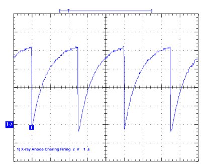 The RC charge time of the Hipotronics power supply is dominated by the 2.5M series charging resistor and the three 0.1uF capacitors in parallel (total value of 0.3uF), which are located in the X-ray Anode oil tank. The calculated time constant is 0.75 seconds. Since the system has a cycle time between pulses of 2.5 seconds, this means that the Hiportronics will charge to about 95% of the set value. It was found that good x-rays were generated for a set voltage of about 25kV (this also corresponded to a meter reading on the main system control panel of about 150kV). A setting of 20kV was too low and no x-rays external to the machine were measurable. (by Randy Carlson)
Randy measured the Primary resistance of H.V. transformer by measuring the current of a DC voltage around the transformer. The value is about 30 miliOhm. Unfortunately we were not successful in measuring the inductance with General Radio Bridge.
No comments:
Post a Comment