Recently UIC purchased a Eurotherm 7100A SCR Controller to replace the no longer supported Eratron FPE 202-D30 SCR Controller. This Technical Note will discuss ways in which to utilize not only the Euroterm Controller but also any generic SCR controller for the charging of the main Thyratron Capacitor Banks. One goal of changing to a commercial controller is to eliminate much of the troublesome Firing Angle and PC Board Control cards that were utilized for the Eratron unit. The Eurotherm unit as ordered is a basic unit without “alarms” or “soft start” features that are useful in driving inductive loads like the HV Transformer. More advanced units incorporate a “safety ramp” that involves progressively increasing the Thyristor firing angle in order to apply the voltage (and current) to the load smoothly and thus reduce the start-up current of loads which either have a low resistance when cold or are inductive. For inductive loads, the “safety ramp” prepares the initial magnetization of the transformer to avoid saturating transformers on power up that can lead to large in rush currents to the primary. This note will show via simulations that it is relatively straightforward to control the present Eurotherm unit and incorporate “soft start” features.
2. Circuit Model Description
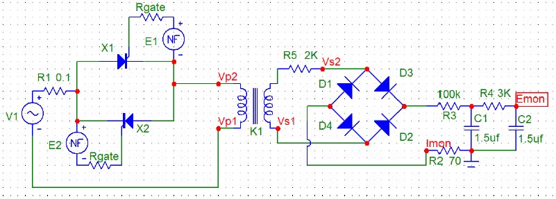 This circuit is essentially the same as that shown in the note “Firing Angle Control of SCRs during Charging”, 26 March 2006. The main addition to that circuit is the generation of the SCR control voltages (E1 and E2) by the Eurotherm unit, which is driven by a 0 to 5 Volt DC control signal. V1 is the 208 VAC rms line voltage and the “ideal” HV transformer has been modeled as having a 32kVAC rms output voltage (turns ratio of 154) with a secondary resistance, R5, of 2K ohms. R1 is the 0.1-ohm peak inrush current limiting resistor to protect the SCRs. The diodes are made up of three SCH20000 diodes in series and labeled as D1 thru D4. R3 is the series-charging resistor of 100K made up of ten; 10K 225-watt wire wound power resistors. The North and South capacitor banks are labeled as C1 and C2 and interconnected with a 3K resistor. R2 is the 70-ohm resistor for purposes of monitoring the pulsed charging current (Imon). The actual Pulse Modulator (PM) HV Schematic of Prometheus (see D-2151) shows a Transzorb 5KP6.0A that clips the Imon signal at a voltage ranging from 6.67 to 7.37 volts. This is done in order to accommodate the Pulse Integrator of the PM HV Control Board (see C-2154). This is not necessary for use of the Eurotherm unit and no feedback current via Imon is needed.
3. Results of Simulations
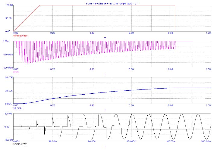 In the event of the SCRs becoming shorted or commanded to full on, the resistor charging string is the only limit to the charging current pulses and the time that it takes for the system to reach a full voltage of 32kVAC rms x 1.414 = 45 kVDC. The purpose of the PM Voltage Control Timing Circuit (see C-2155) is to limit the charging time available with the SCRs commanded to full on such that the Thyratron Bank Voltage as indicated by Emon never exceeds 30kV although the Anode rating of the CX1622 Thyratrons is 35kVDC. This time should include the “soft start” feature of about 8 full SCR firing cycles or 0.133 seconds. The results of a simulation showing the SCR Firing Angle (set at 180 deg), the Imon current pulses, the Emon charging voltage, and the first 0.2 seconds of the Transformer Primary Voltage, gives a maximum desired charge time of 0.820 seconds. The Top trace (Red) shows the Firing Angle ramping up to 180 degrees in 0.133 seconds with the corresponding Transformer Primary Voltage being given a “soft start” over 8 full cycles as shown in the Bottom trace (Black). The Imon current pulses are shown in the 2nd trace (Magenta) and charging resistor limited to 420ma with the Emon voltage of the 3rd trace (Blue) indicated at the complete charge of 30kV in 0.82 seconds.
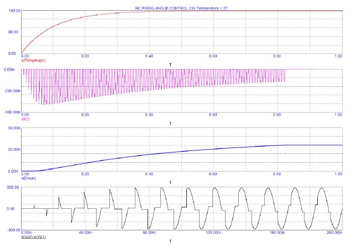 If the SCRs or the Controller fails such that the SCRs stay on, then the only protection to stopping the charging cycle of the capacitor banks is to command open the AC Contactors that drive the input to the HV transformer. This means that if the Emon voltage continues to increase after 0.82 seconds, the contactors must open before 1.25 seconds, which is the time that the system will reach 35kVDC on the Anodes of the Thyratrons. Some sort of comparator circuitry for Vref and Emon would appear to be needed to actuate the opening of these HV transformer contactors. Although a version of this circuitry exists on schematic C-2154, there are simpler ways to implement this fault protection. One way that is already being used is that the Thyratron banks are being fired just after the time when the charge is complete.
Although it might seem complex to generate a ramp for the firing angle control, a simple pulsed RC circuit (time constant about 0.2 seconds) driven by the present Output Transistor of the PM Voltage Control Timing Circuit (see C-2155) could be utilized. The results are shown on the bottom four plots on the next page and can be compared to those at the top of the page for the linear ramp of the “soft start”. Note that any additional complexity in ramping the top of the firing angle voltage is not necessary since ALL SCRs and Diodes are being operated safely within their limits.
(Written by Randy)
No comments:
Post a Comment