Monday, November 27, 2006

New timing setup for beam stabilization system

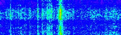
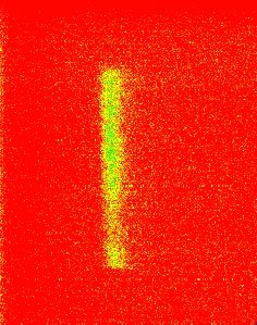
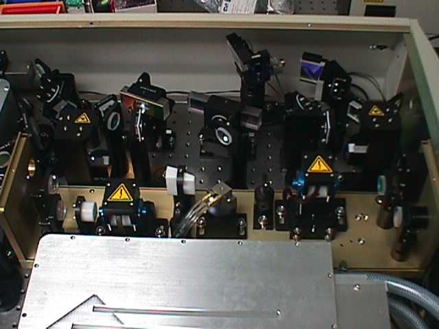
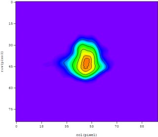
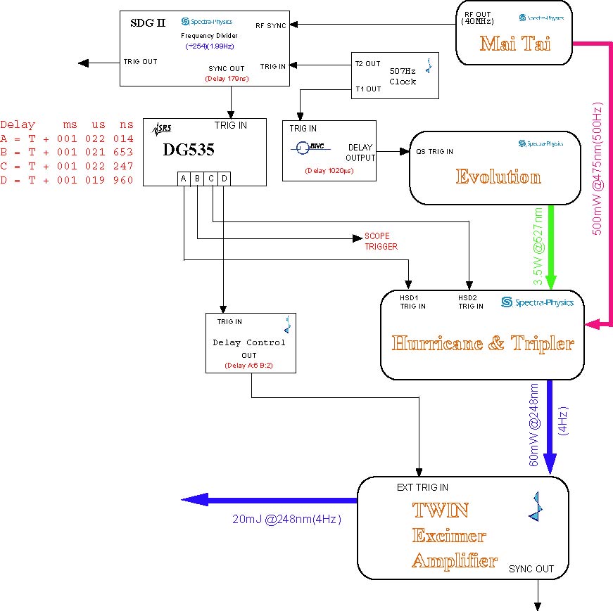
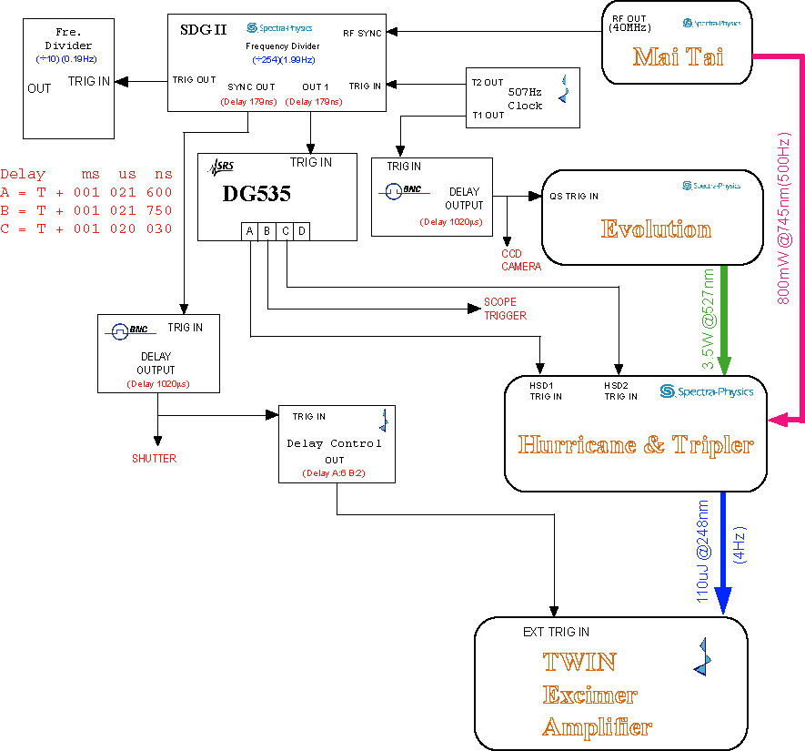
The beam stabilization system needs control signals from SDG II "out 1" and "sync out", so I have to change the timing again. I already modified the timing for the front end before (on July 7th), but I did not consider to trigger the Pockcel and TWIN AMP separately. Now I have to insert one more delay box such as BNC delay generator in order to trigger the TWIN AMP.

The beam stabilization system includes one CCD camera and one chopper, both of them also need the TTL pulses to trigger. The pulses from BNC #1 to trigger CCD, #2 to trigger the beam chopper.

Wednesday, November 15, 2006

JLab FEL Breaks Power Record

The most powerful tunable laser in the world has shattered another power record. Officials report that the free-electron laser (FEL) at the Thomas Jefferson National Accelerator Facility produced a 14.2 kilowatt beam of laser light at an infrared wavelength of 1.61 um on Oct. 30.

Tuesday, November 14, 2006

Heater and reservior voltage for TWINAMP

The TWINAMP could not be triggered by internal pulse correctly but only by external signal normally yesterday. By my early experience, the problem was caused by the thyratron heater and reservoir voltages. We measured the heater voltage(V_H) from the power supply output, which is about 10.2 VAC. When I decreased this voltage down to 9.4V (the minimum adjustment), the TWINAMP ran well. We also measured the voltages from thyratron side.


Power Supply OutputBefore filterBefore Thyratron
V_Heater(VAC)9.307.807.50
V_Resevior(VAC)7.787.487.48

On May 1st, I set the Heater and Reservoir voltages: V_H=11.35V, V_R=8.35V. On Oct. 18, 2005, we set the voltages: V_H=7.05V, V_R=7.49V.

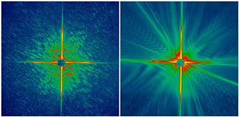
Ultrafast, Intense Laser Captures Nanoscale Images

HAMBURG, Germany, Nov. 14, 2006 -- Using a single, extremely short and intense x-ray laser pulse, an international team of scientists have, for the first time, taken a high-resolution diffraction image of an object such as a protein before the intensity of the radiation destroyed the sample. The experiment was the first successful application of "flash diffractive imaging" and begins a new era in structural research.

The new method will be applicable to atomic-resolution imaging of complex biomolecules when even more powerful x-ray lasers, currently under construction, are available. The technique will allow scientists to gain insight into the fields of materials science, plasma physics, biology and medicine.

The scientists, part of an international collaboration led by Lawrence Livermore National Laboratory's (LLNL) Henry Chapman and Janos Hajdu of Uppsala University in Sweden, achieved the feat using the world's first soft x-ray free-electron laser, located at the FLASH facility at Deutsches Elektronen-Synchrotron (DESY) in Hamburg. Their work will appear on the cover of the December issue of the journal Nature Physics (12 November 2006 | doi:10.1038/nphys461).

The experiment suggests that in the near future, images from nanoparticles and even large individual macromolecules -- viruses or cells -- may be obtained using a single, ultrashort high-intensity laser pulse before the sample explodes and turns into a plasma. This means that scientists could better understand the structure of macromolecular proteins without crystallizing them, which is required in conventional x-ray structure analysis, and have the ability to rapidly study all classes of proteins.

(From Photonics.com)

Friday, November 10, 2006

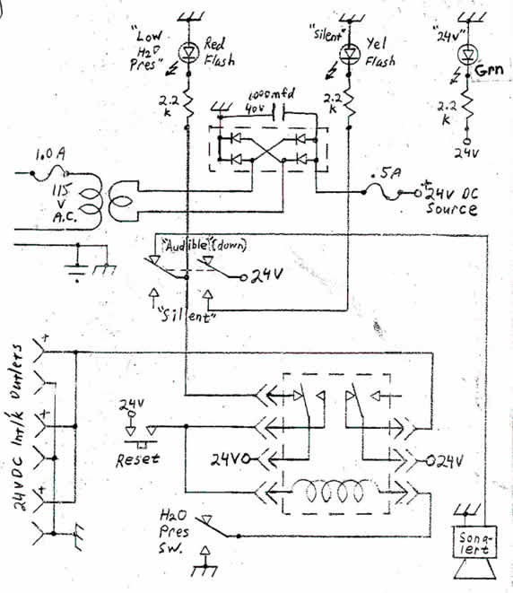
Low water pressure alert system

The water pressure alert system has been used in our lab for many years. When the city water pressure is low, the system will buzz loudly, then the 24V control signal will be shut down. This alert system looks simple but very useful. It is used to protect the diffusion pump water cooling for x-ray and YAG laser water cooling system.

From last week, the alarm kept buzzing. I had to set the alarm to silent. I opened the circuit box to check today and found the problem came from the reset button. When I pushed the button, the reset could not be short. So even the water pressure sensor operated well, the 24V power could not be applied to the relay coil. The alarm was recovered after the reset button was replaced.

Thursday, November 09, 2006

Replaced Hurricane compressor grating

Due to the air humidity, the compressor grating absorbed some dust, this finally decrease the reflection efficiency. We replaced the old grating with the brand new one ordered from Spectra-physics. The measured power before compressor is about 500mW, after the compressor, the power is 300mW, which is bigger than 260mW using the old grating.

The power was decreased to 250mW when I added the 1.02ms delay for diode pump laser. After the delay time adjusted accurately, the power recovered to 300mW. The new delay time is 1020.2us.

Wednesday, November 08, 2006

Leak from Alumnium box

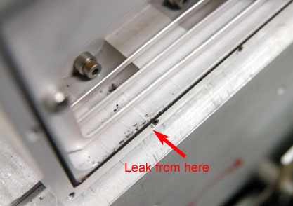
We cleaned all TWINAMP windows, filled 400mbar F2 + 1400mbar He for leakage detection last night. We found the pressure was dropped by 50mbar for the long tube, and we could smell pungently. Because the o-rings for window and PVDF plate were changed last month, maybe the gas leak came from the aluminum box connected to the window frame. We found some black grain in the aluminum box. The o-ings were changed immediately.

Tuesday, November 07, 2006

O-ring sizes for TWINAMP

#1. between PVDF frame and Al box
#2. between Al box and 2nd plate
#3. between 2nd plate and PVDF plate
#4. between PVDF plate and window

For Short tube: window size 75 x 40 x 5.1
#1. 60 x 2
#2. 120 x 2
#3,4. 64 x 2 (if the opening on the end plate and PVDF is 65)
60 (or 62) x 2 (if the opening on the end plate and PVDF is 60)

O-ring between reservoir and PVDF fram: 410 x 4
O-ring between PVDF reservoir and upper ground plate: 400 x 4

For Long tube: window 100 x 50 x 10

#1. 85 x 2
#2. 125 x 2
#3,4. 85 x 2

Monday, November 06, 2006

Repolished the TWINAMP long tube windows

We removed t he winodws from TWINAMP lone tube, and found they were very dirty. The small black grains on the surface like last time. There was a thin gray film on the inside surface when we looked the windows at the grazing angle. This film could not be removed by normal optical cleaning method. So we tried to repolish it using 1 micro power. After repolishing, the surface looked very smooth.

Thursday, November 02, 2006

Pulse measurement for final amplifier

The Prometheus gases has been changed.

We calibrated the energy meter for large target chamber, it's about 30 times between the outside meter and the real energy. The output energy from the front end is about 16 mJ, the high voltage of Prometheus is 22 kV. The measured energy before the target nozzle is ~ 220 mJ.

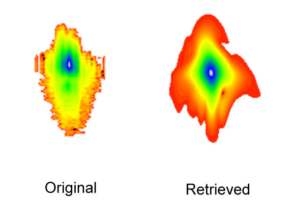
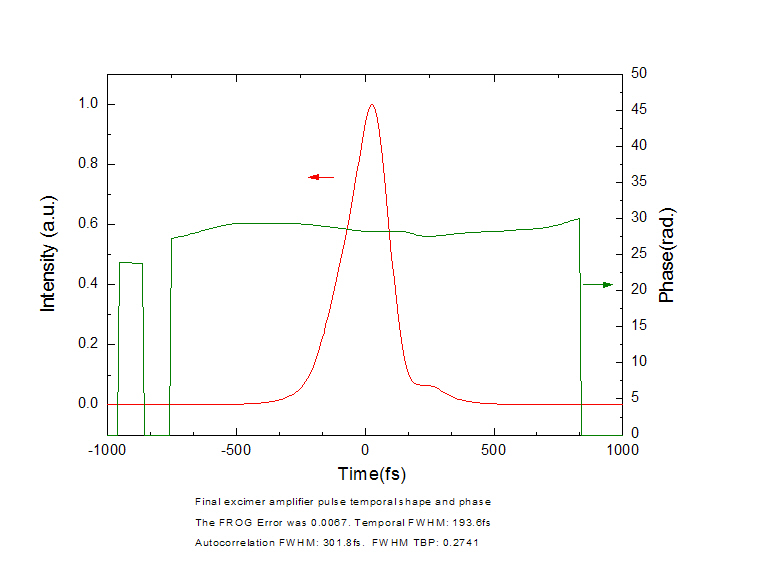
The time duration and the phase were measured by FROG. The raw data and the retrieved data looks similar. Compared the front end measurement, the pulse was enlarged because of the dispersion. The pulse width is around 190-220 femtoseconds, the phase kept flat.

Wednesday, November 01, 2006

Laser Focus World introducing my blog

The column writer, Ms. Gail Overton introuded my blog on Laser Focus World in October.

Tuesday, October 31, 2006

Snapshots of laser wakefields

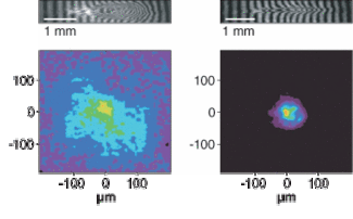
Electrons, protons and even ions can be accelerated using the extreme electric fields generated when a high-power laser is focused into a plasma. But the structure of the so-called laser wakefields that are driven through the plasma at almost the speed of light — analogous to the wake produced behind by a boat as it travels on water — has until now only been discernable through simulations of the process. Nicholas Matlis and colleagues have produced the first direct images of a laser wakefield, by using a holographic technique that reconstructs an image of the wake structures from the way in which they perturb the interference of two coherent light beams passing through the plasma. The technique provides a new tool for studying laser–plasma interactions and potentially improving the performance of laser-driven particle accelerators.
Nature Physics Published online: 2, 749 - 753 (October 2006)

TWINAMP window holder design


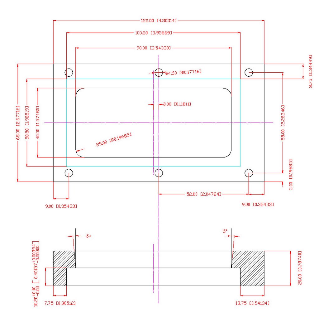
Because the thickness of the MgF2 window for long tube was different, the old holder can not be used. Excepting the thickness, the other dimensions should not be changed anymore. The material: Aluminum Plate (Al Zn Mg Cu 1.5). Surface: good quality (milled profiles)

Monday, October 30, 2006

Leybold TRIVAC D16B pump

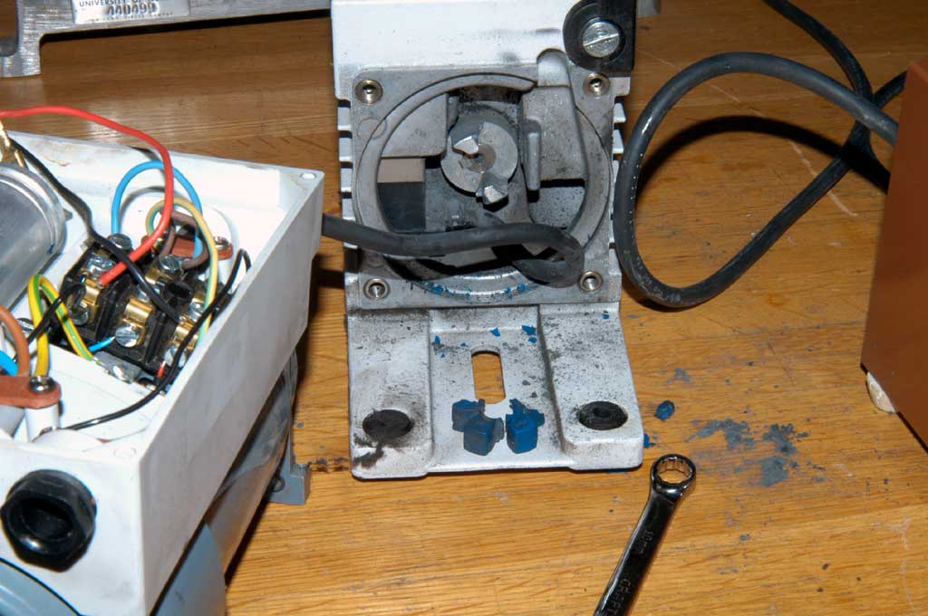
We used the rotary vane pump to vacuum the first spatial filter for TWIN system, this pump could not work two weeks ago. At first, we guessed the start capacitor was broken, however the pump did not work any more even we changed a new capacitor. Mike helped to separate the motor and the rotary vane, he found the motor worked well. The problem was the spider coupling was broken.

Tuesday, October 24, 2006

FROG measurement using new CCD camera

We used the new FLI back illuminated CCD to take the FROG picture. I found this new CCD camera very sensitive to the UV light compared with our old CCD. For the old one, we had to expose about 5 seconds to take Hg I 248 nm line, for this new one, it's only about 30 ms.

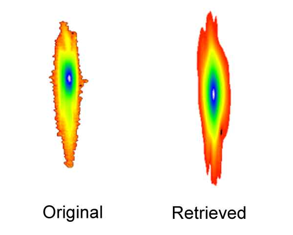
When we were taking the FROG images, the signal was very strong. I had to use a ND filter (~0.005 transimission) to attenuate the light. The retrieved data is almost match the raw data. But for the old CCD camera, it's not well to match these data.

Tuesday, October 17, 2006

MaxCam CM 1-1

In order to measure the UV beam effctively, we bought a low cost, high QE, back-thinned CCD camera from Fingre Lakes Instrumentation.

Camera Serial Number: 2357 04
Sensor Type: Class 1 / 512 x 512 / 24um pixels E2V CCD 77-01-1-390
Lab Ambient Temperature: 23 C

Setup measurement
Temperature sensor ok: checked
Shutter opens fully: checked
Shutter closes fully: checked
Window clean on both surfaces: checked
CCD free of dust: checked

Purging
0.2 torr rise time > 90 seconds: checked
Fresh desiccant: checked
Argon filled: checked

Mechanical/Cosmetics
No scratches or marks on Case: checked
Shutter test properly: checked
Serial number label is present: checked

Image Quality
CCD test temperature: -15 C
Camera achieves T greater than: 37 C
Mean bias level of bias frame: 2367
Standard deviation @ test temp, small area: 3.3
Mean saturation level: 65535
Noise distribution is random: checked
Bias frame histogram is Gaussian: checked
Standard test target appearance ok: checked
Bias over scan frame saved as 2357 04 bias OS -15C. fts
Light frame saved as: 2357 04 lgt -15C.fts
Flat field frame saved as: 2357 04 ff -15C.fts

Software A/D serial Number: #3329

Final Check, no frost visible@ -15 C


Tested by: Dave Johnson October 13, 2006

Thursday, October 12, 2006

Vacuum pump for first spatial filter

We found the vacuum pump for TWIN first spatial filter does not work. I guessed it's caused by the motor start capacitor, unfortunately this kind of cap was from Europe.

Driving electron beams to 1 GeV

Progress continues apace in the development of laser wakefield accelerators, which produce high-energy beams of electrons, atoms and molecules using the extreme fields generated in a plasma by high-power lasers. But for the potential of these devices to be realized — in practical applications that range from studying the behaviour of matter under extreme conditions to proton therapy for the treatment of deep-seated tumours — the energy of the particle beams they produce must reach the giga-electronvolt range. Initial estimates had suggested that reaching such energies would require lasers capable of producing pulse powers of the order of petawatts. But Wim Leemans and colleagues have proved the predictions wrong by producing 1-GeV electron beams using only 40 terrawatts of laser power — the trick being to focus the laser into a 3.3-cm-long gas-filled capillary discharge tube.

Nature Physics 2, pp696 - 699 (2006)

Uranium Beam-Pumped UV Laser

Lasers consist of an active medium of excitable atoms, a pumping mechanism for exciting those atoms, and a cavity for building up a pulse of coherent radiation. At the Institute for Heavy Ion Research (Gesellschaft für Schwerionenforschung, or GSI) in Darmstadt, Germany, scientists have succeeded for the first time in using a beam of uranium ions as the pump for producing ultraviolet laser light.

It works like this: the uranium beam ionizes argon atoms, which ionize krypton atoms, which in turn form excited molecules with fluorine. The krypton fluoride molecules are the excited entities which emit coherent light at a wavelength of 248 nanometers. A laser that uses this rare gas-halide mixture is called an excimer (excited dimer) laser.

This is not the shortest laser wavelength ever achieved, and the uranium pumping scheme is not all that energy efficient. So why then use this approach to producing laser light, especially when electrically pumped commercial krypton fluoride lasers are available? Because this was a test run for producing laser light in excimers that can't be electrically pumped.

According to Andreas Ulrich of the Technical University of Munich (andreas.ulrich@ph.tum.de), the goal is to excite excimers of pure rare gases for producing radiation in the VUV (vacuum ultraviolet) and soft X-ray region of the spectrum. Only now have uranium beams at GSI been powerful enough to provide the pumping power for lasers in this wavelength region. Being so heavy, uranium atoms deposit their energy into a gas much more efficiently that lighter particles such as electrons.

Ulrich et al., Physical Review Letters, 13 October 2006
Contact Andreas Ulrich
Technical University of Munich
andreas.ulrich@ph.tum.de

Copied from Physics News Update 796 #2, October 11, 2006 by Phil Schewe and Ben Stein

Tuesday, October 10, 2006

Compound Refractive x-ray Lenses (CRLs)

The compound refractive x-ray lenses (CRLs) are used to focus and collimate hard x rays, and image objects using hard x rays. The lenses have been experimentally shown to operate in energy ranges from 4 to 80 keV, at focal lengths as small as 5 cm, with numerical apertures of 10-3 or better. These operational ranges can be further extended.

The main principle behind compound refractive lenses (CRLs) is an ability of a group of thin lenses to greatly shorten the focal length. A series of N lenses with small apertures is used to achieve both one- and two-dimensional focusing and imaging at x-ray photon energies, where refractive imaging has previously been thought to be impossible due to the weak refraction of x rays. Note that the refractive index for x-rays is less than 1.

Therefore, unlike visible light optics which will cause visible rays to diverge, the concave lens will focus x-ray photons. Among the lenses we offer are cylindrical, spherical and 1- and 2- dimensional parabolic units.

From Adelphi Technology Inc.

Friday, October 06, 2006

Relay K4 on South side replaced

After running one hour, the Prometheus system was shut down. The Filament light was on and the south bank was totally off. The system was recovered just after changing the relay K4, which is the power controller.

Thursday, October 05, 2006

Wednesday, October 04, 2006

Obtaining the first order spectrum

We tried to record the first order spectra many times, however we only got a single spectral line. Today we reduced the gas pressure and moved the focal spot a little behind the nozzle center, we also increased the MCP voltage(~1 kV) and phosphor voltage (~4 kV). We observed the soft x-ray spectrum successfully, we will calibrate these spectra soon.

Sunday, October 01, 2006

Bright zeroth order spectrum

We installed a new parabolic reflect mirror to focus the laser beam and adjusted the alignment of the spectrometer. In order get the signal, we changed the nozzle repetition rate to 0.5 Hz, the gas pressure decrease around 100 psi. Compared the last zeroth order spectrum, this looks very bright and sharp. The line became very weak when the nozzle was not triggered, it means that there was only 248 nm laser hit MCP.

Unfortunately, we could not find any interesting spectra when letting the spectrometer scanned in the whole range.

Tuesday, September 26, 2006

Leak from the McPhonsen spectrometer

We tried to vacuum the McPhonsen 247 over night, however there was a big leak from the bellow connector.

Ping thought the leak from the bellow, so he changed a new bellow. After than, he found the threads of two screws for mounting the bellow were badly damaged, which mainly caused the leakage.

After he put two new screws to tighten the bellow flange, vacuum of the pump system reached 3*10^-5 in 20 minutes.

Monday, September 25, 2006

Zeroth order spectrum form VUV spectrograph

We are using a 1-meter 86 degree grazing incidence model 247 McPherson spectrometer to measure the soft x-ray emission from laser plasma interaction. The detector is a single stage 2 inch diameter MCP with a potential of between of 200V to 1kV across it. The electron burst from the MCP is accelerated by another potential of 3 kV to 5 kV into a phosphor screen. The green photons from the phosphor is collected by a camera lens and sent to CCD camera. By adjusting the spectrograph, we obtained the 0-order spectrum.

Thursday, September 21, 2006

That's no laser, it's a particle accelerator

That's no laser, it's a particle accelerator

Geoff Brumfiel

Israeli physicists have turned a laser into a particle accelerator. Dubbed a paser — for particle acceleration by stimulated emission of radiation — the device accelerates bundles of electrons using the same principle as a laser.

At present it can only accelerate electrons by about 0.15% of their initial speed, but it could lead to compact particle accelerators and tabletop X-ray devices, according to Samer Banna of the Israel Institute of Technology in Haifa. He and his colleagues will publish their work in Physical Review Letters.

Conventional lasers exploit the quantum properties of atoms. An energy source is used to boost the electrons in a group of atoms into an elevated energy state. Passing light in the form of photons stimulates the atoms and causes the electrons to fall back to the lower energy level, emitting more photons in the process. These in turn stimulate more atoms and so on, so that a large number of photons are emitted. The photons are all identical, which makes the beam of light uniform.

Pasers work on a similar principle, but the output is accelerated electrons. Packets of electrons are fired into a cloud of excited carbon dioxide gas. As in a laser, the gas releases a large number of identical photons. But those photons are instantly absorbed by the passing electrons, which get an energetic kick, and leave the device moving more quickly than when they came in.

The fact that the paser uses atoms to speed up electrons sets it apart from other particle accelerators. "This is unlike anything that's come before," says Eric Colby of the Stanford Linear Accelerator Center in California. The unique mode of action makes the paser far more efficient than current machines, which achieve acceleration by generating enormous electric fields inside huge cavities. Colby is optimistic about the paser's potential. "It's a pretty small effect now," he says, "but there are strong technical reasons to believe that a very significant gain in acceleration is possible."

Levi Schächter, of the Israel Institute of Technology, believes that the paser could also make its mark as a source of X-rays. If the high-speed electrons have their paths bent after they leave the device, they will release a laser-like beam of X-rays that could be used for medical or nanotechnology applications. But Schächter is reluctant to guess exactly what may come of the technology. "In Hebrew we say, 'It's difficult to make predictions, particularly regarding the future'."

It wouldn't be possible to produce the exact equivalent of a laser beam with electrons — the Pauli exclusion principle states that electrons cannot exist in the same energy state at the same time. But laser equivalents can in theory be created for other types of particle, such as gravitons (which carry the gravitational force), phonons (packets of vibration) or some nuclei — if a system can be found that emits them. In June, for example, a group of researchers reported building a sound laser, or saser, that uses semiconductor technology to create a uniform beam of phonons (A. J. Kent et al. Phys. Rev. Lett. 96, 215504; 2006).

Colby says that these new systems show that it is easier than one might think to generate laser-like behaviour. "If you can store energy in a material," he says, "a great many things can be done."

Wednesday, September 20, 2006

Grating Cleaning Procedure

David found the compressor grating became dirty, that caused the output energy lower. He suggested to order a new grating or clean the grating. We ordered a new grating from Spectra-Physics, the model number is 9800-2680, the size is 30x110x16. The grating cleaning procedure is listed below.
----------------------------------------
Direct Contact Method:

Spectra-Physics RGL provided the direct contact method and they have used it on gratings with
minor dirt or oil contamination.

1. Select a pan large enough to accommodate the grating as well as being able to allow unrestricted movement around the grating. A 20cm x 20cm x 5cm (8" x 8" x 2") aluminum baking pan was used here.

2. Heat water temperature to 32 C (90F) +/-1C.

3. Mix together Woolite 2 capfuls of (or equivalent) with water.
http://www.fabriclink.com/Woolite/Home.html in case one is not familiar with Woolite.

4. Place grating in the soapy water pan.

5. The water should cover the top surface of the grating by 10-12mm.

6. Adjust water level in pan accordingly and maintain water temperature of 32-34 C.

7. Grating is to be lightly stroked with a cotton ball in the direction that is parallel to the groove.

7.1. Note: "Stroking" means to drag the cotton ball across grating, applying no physical pressure, allowing just the weight of the wet cotton to contact the grating surface.

8. Remove the grating from the soapy water pan and rinse with distilled water. Make sure that the water is flowing down the grooves, not across the grooves.

9. Rinse the grating with isopropyl alcohol (rubbing alcohol 70% by volume) with the alcohol going down the grooves not across. Be careful for the alcohol will dissolve the ink on the grating. I would advise that one write the groove density on the grating with a pencil.

10. Blow dry the grating with nitrogen (or clean "air") starting at the top allowing the alcohol to run down the grooves. As with the rinsing, blow down the grooves not across them. When testing this method at SPMV, dry nitrogen at a pressure of 50 psi through a 6mm dia. nozzle was used. This dried the grating well.

Bake Out Method

The bake out method is generally used when the grating exhibits a film or 'fog' on the surface of the grating. The cause and/or composition of this film is unknown. However, baking out the grating usually results in the elimination of the film.

Place gratings in the oven with the gold surface up. Take care when placing the gratings so that the gold surface does not come in contact with anything.

Ramp up oven over at a 2 hour rate to 105 C.

Bake the gratings for 2 hours at 105 C.

Ramp down the oven at a 2 hour rate to room temperature.

Hurricane Compressor alignment procedure

The compressor consists of one grating, one horizontal retromirror set, and one vertical retro-mirror.
(1). Adjust the grating position horizontally and rotate the grating so that the input beam on the right bottom. The first order diffracted beam out of the grating should be centered on the horizontal retro-mirror without clipping of the spectrum.
(2). Morve the horizontal retro-mirror so that the spatially dispersed spectrum on the grating left bottom. The spectrum on the grating should be the same height as the input beam.
(3). Move and rotate the vertical retro-mirror so that the beam is retrace back to left top of the grating. Make sure the vertical retro-mirror is positioned as close as possible to the input beam without clipping the input beam.
(4). The beam coming out the compressor should be centered to the output port of the Hurricane with beam height equals to 4".
(5). If the beam height is not centered to the output port, one can adjust the y-axis of the vertical retro-mirror to center it.

How to adjust the Hurricane regen

(1). Blcok the Mai-Tai seed beam.
(2). Disable the Pockel Cell trigger.
(3). Taken the half-wave plate from PC1 postion, put it behind PC2, then rotate this plate to maximumize the output power. (in our case, ~550mW@745nm in free running).
(4). Tune the Evolution green beam last steering mirror to peak the output power.
(5). The output power should not be decrease when centering the iris.
(6). Adjust the half-wave plate to reduce the power minimum.
(7). Mark half-wave plate, then move it back to PC1 postion.
(8). Adjust the seed beam steering mirrors to make the time gap between free runing pulse and seed pulse around 70 ns.

Monday, September 18, 2006

Replaced X-ray gun ion gauge

Because the old ion gauge for x-ray gun did not work stably, I ordered a new ion gauge from MDC. The old gause was replaced as soon as I got this new gauge. The vacuum reached around 3x10^-5 Torr before I left the lab.

For LLG-TWIN, I have to change the gases twice to make sure the timing trigger steadily. The laser energy would be decreased in a couple of minutes after first gas filling, then it's hard to synchronize the seed beam and the TWIN. After evacuating the chamber and refilling the gases, the TWIN became better.

Saturday, September 16, 2006

Timing delay for target nozzle

In this week, we tried to focus the laser beam to the Xe cluster for measuring the Xe(L) emission. Because the nozzle has been changed, the timing delay between laser pulse and nozzle trigger must be adjusted. On Monday this delay time was about 478 us, however it changed to 410 us next day, on Friday the dealy was 491us. The range is around 10 to 80 us, beyand these values, we saw nor Xe(M) light on the top CCD neither any singals from crystal spectrometer (for measuring L-shell light).

Wednesday, September 13, 2006

Trigger signals from frequency divider

Sometimes the signal from the frequency divider was strange. We used two frequncy divider, No.1 is 2 times divider, No. 2 is 10 times. The seed pulses with 4 Hz repitation rate was divided to 0.2 Hz by these frequncy dividers. I found the No.1 sent disordered signals. After moved this divider from one rank to the another, the problem was disappeared. So I used the same DC power supply to energize these dividers now.

The Relay K4 for cooling fans could not run well, previously it became well after only tightening the connectors. Yesterday I had to tighten many times, I replaced it this morning.

Wednesday, September 06, 2006

Windows cleaning and O-rings changed

I removed the windows of both tubes. The windows of the long tube are a little bit dirty, maybe the energy dropping was caused by the leakage. The most possibility is the leak from the windows. Firstly it's diffcult to take the window from the holder, I dropped some ethonal into the gap between window and the holder, the window became loose and was easy to remove. I cleaned windows carefully. Unfortunately I found there was a light breakage inside the window, we should order new window for the long tube.

I installed all windows in the afternoon, and made the passivation for both tubes. Before my leaving I filled the Helium into the chambers by 1500 mbar for leakage checking. I will continue to passivate the tubes.

Tuesday, September 05, 2006

TWIN windows became dirty again

After the labor day, we tried to continue the experiments. So I filled the new gases into the TWIN excimer amplifier this morning. The output energy of the front end was 34.7 mJ, Alex already used this beam to align the target and x-ray spectrometer. Unfortunately, the energy was dropped to 7.7 mJ suddenly in the afternoon, I found there were small dust grains on the long chamber windows, which was similar to the status two weeks ago (on Aug. 22th). I cleaned the same windows on May 10th (http://xysong.blogspot.com/2006/05/twin-dirty-windows.html). It is very strange that the windows became dirty frequently. I guess the filter was dirty or something wrong inside the long tube.

Wednesday, August 30, 2006

Obtaining the Xe(L) spetra successfully

The laser system ran very well today. The front end output a laser beam with about 26 mJ energy. After the Prometheus amplifier, the energy reached about 360 mJ as energizing 25 kV high voltage. Today the total shots is 1218, no misfire happened. The filament was shut down in the beginning, I could hear the click from the filament relay, after turn on again, the problem disappeared.

Because the nozzle was changed, I adjusted the timing delay for optimizing the Xe(L) outputs. Alex took many spectra from the target side.

Tuesday, August 29, 2006

Seed beam focal spot measurement

The seed beam was sent to the target chamber after expanding beam size from 3 cm diameter to around 10 cm diameter, then it was focused to the smaller spot by a Parabolic mirror. We are using the 248 nm coated paroblic mirror with 20 cm focal length, so the focal spot under the diffraction limitation is about 1.2 um.

In order to measure the focal spot, we put a 40X microcope objective lens behind the spot. A CCD camera without a window to record the spot image, the CCD size is 510x492, the pixel size is 9.6 um x 7.5 um. After calculation, the focal spot is about 2.9 um x 3.8 um.

Friday, August 25, 2006

Monday, August 21, 2006

Tightening LLG-TWIN thyratron plate and ground plate

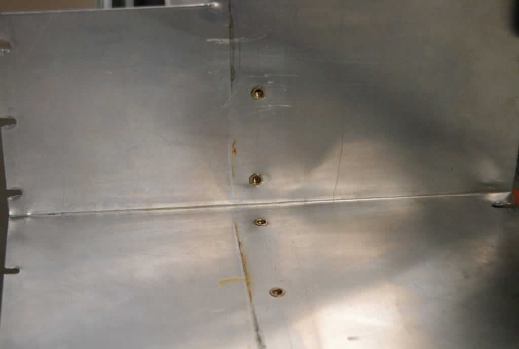
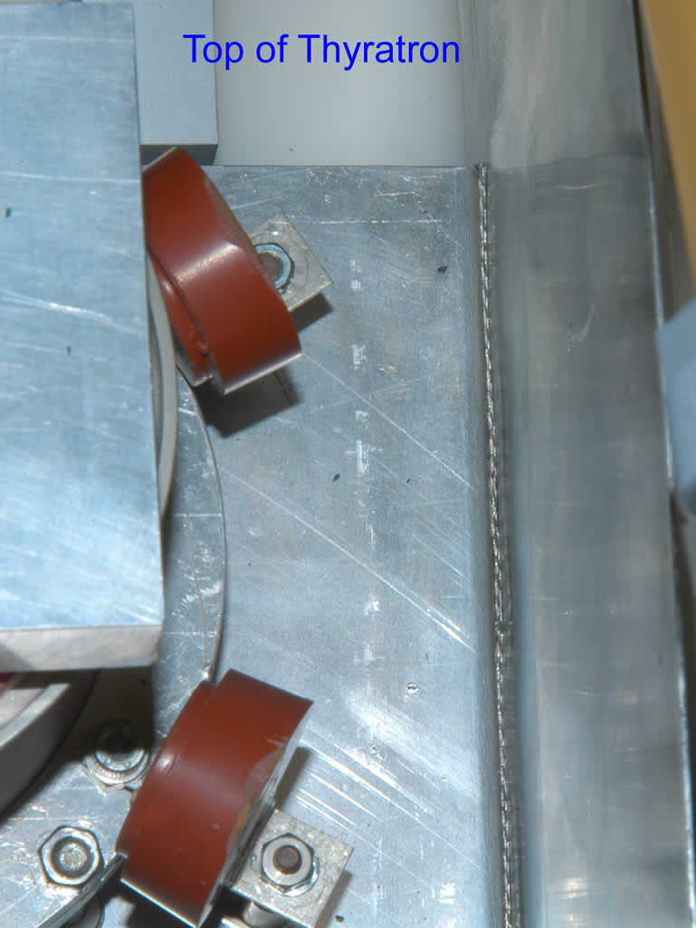
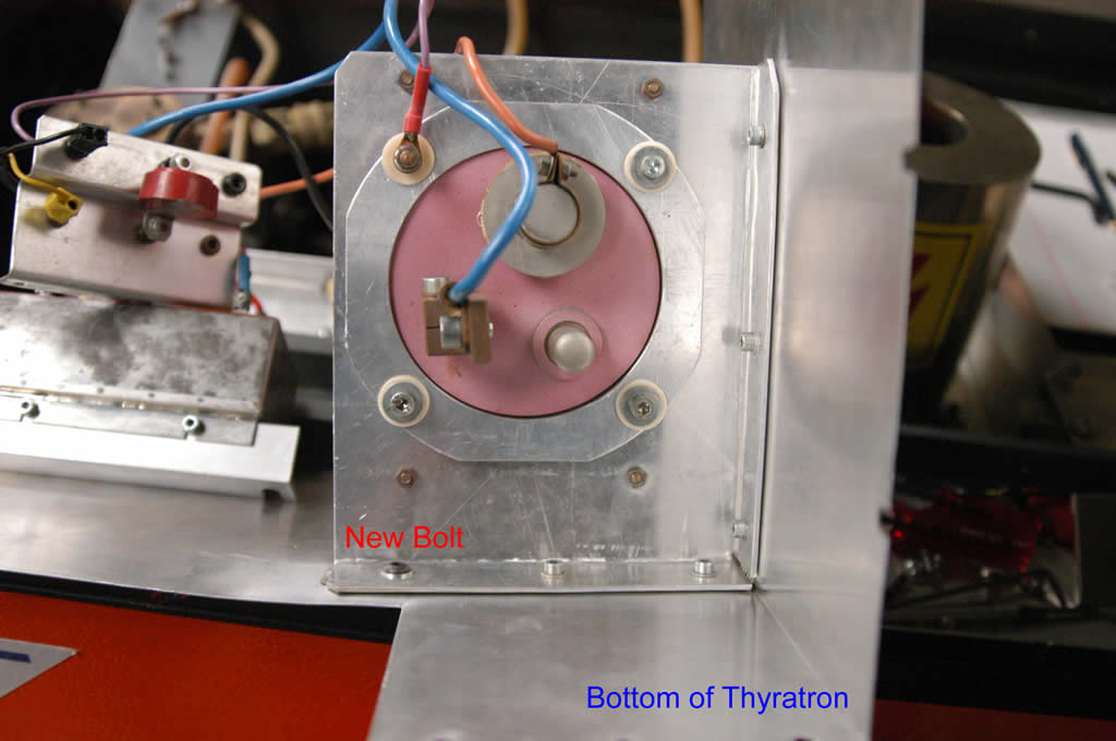
Last month, we found the arcing problem when running the LLG-TWIN excimer amplfier, I put a teflon plate for preventing the sparks. Today the arcing happened again, I am afraid the isolation plate could not really avoid the arcing. With Randy and John's helps, we removed the alumina plate and found the spark traces on plate of thyratron side.

We polished the plate surface and punched a new hole for conbine the plates tightenly. A wire braid was inserted between the plates in order to avoid the arcing.

Finally we fixed the arcing problem, however the output energy was still low and the beam quality was very bad. When I checked the lone tube windows I found there were some dark grains on the window surface. I want to open the chamber to clean them tomorrow.

Wednesday, August 16, 2006

Front-illuminated CCD or Back illuminated CCD?

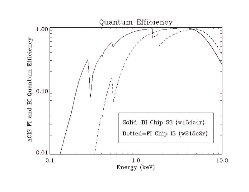
A conventional CCD consists of a sandwich of semiconductor layers overlaid with a network of "gates", electrodes which serve to transfer charge from one pixel to another as the device is read out. At low energies (E<1>5 keV). due to photon loss through the front of the back-illuminated device.

Comparison of QE of front- and back-illuminated CCDs. The lack of gate structure at the exposed surface of the back-illuminated device, combined with its reduced physical thickness, results in improved QE for energies <3>5 keV), due to photon loss through the front of the back-illuminated device.

copied from http://cxc.harvard.edu/newsletters/news_05/node11.html

CCD detectors are not able to convert all of the photons that strike the surface into electrons for a variety of reasons. Quantum efficiency (QE), which describes the ability of the CCD to turn photons into a useful form of output, is basically the ratio of incoming photons to those photons actually detected by the CCD. The typical range of efficiency is from a few percent up to 90%. Efficiency will also vary with the frequency of light (color) observed. Front-illuminated thick chips are not as sensitive to blue light as they are to light with longer wavelengths.

Interested link:
CCD glossary

Friday, July 21, 2006

Changed the H.V. cable

I found a spare cable in the lab, so I just replaced the burnt cable with it. But the plug body connected with the power supply was borken, so I replaced it with the plug body of the burnt cable.
    

Wednesday, July 19, 2006

TWIN H.V. cable burnt

In the afternoon, the TWIN excimer amplifier suddenly stopped firing after running for half hour. I found the power supply light became red, the light was off after pressing the reset button. Then I pushed the H.V. button and Laser button, I heard a buzz sound inside the excimer chamber. I energized gradually to the amplifier, the voltage reached 12 kV, the buzz appeared again then the system shut down immediately.

I opened the chamber, and turn on the system to check where the buzz came from. I found the high voltage cable was burn, the buzz was from the broken cable. The arcing from the cable caused the fail in high voltage increasement.

Tuesday, July 18, 2006

Arcing from LLG-TWIN excimer inside

When I ran the TWIN excimer amplifier, I could hear the crack sound inside the chamber. This phenomenon was happened before, which was caused by the spark from the Thyratron plate and ground plate. I put two picece of plastic sheet to isolate them. Probably the sheet became dirty or they were too thin. The Thyratron plate should be tightened with the real ground plate in order to avoid the spark, however it will take several days to remove the plate to drill the holes for tightening. The simple way is to replace the isolating plate with a new teflon plate. After replacing, the system ran well.

Friday, July 07, 2006

Modification of front end timing

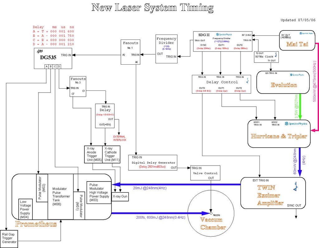
In order to synchronize the seed pulse and Prometheus ASE, I tried many ways without using more delay control equipments. But all the attempts were failed, I have to consider change the front end timing. By studying the old system timing, I found a 10ms delay was added to the CAP pump Q-switch laser, I could copy this setup for our new system. So I inserted a 1ms delay by using BNC delay controller, then replaced the original delay controller from LLG with SRS DG-535. The channel A of DG-535 was used to switch Pockell in and channel C for Pockell switch out. The output of channel D was used to control the excimer control box.

We will have extra 1 ms time delay for the Prometheus trigger and target nozzle controller.

Wednesday, July 05, 2006

Overlapping seed beam and Prometheus ASE

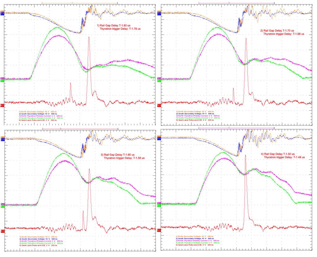
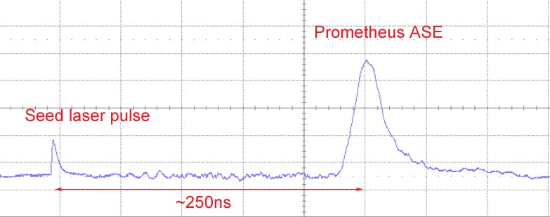
I tried to match the seed laser beam and the Prometheus ASE. The Prometheus ran in the good condition when Thyratron trigger and X-ray Anode trigger was set by 1.78 us and 1.22us earlier than Railgap trigger respectively. So the time delay between seed pulse and Prometheus could not be set less than 1.78us. I tried to adjust the time delay from 1.8us to 1.5 us (as shown in the pictures). I found when time delay was 1.5us, two pulses were overlapped, but the thyratron current wave forms indicated the Thyratron had no time to totally turn off.

The best solution is to add an extra time delay in the front end.

Monday, July 03, 2006

Timing Diagram

We simplified the timing setup when we installed the new High Voltage power supply. The prevent circuit has been removed, the Thyratrons were triggered directly by the signal pulses from SRS DG-535. The repetition rate was decreased by 0.2 Hz for Prometheus, the 4 channels were set as A=T+1 ms, B=A-1.75 us, C=B+30 ns, D=A-1.21 us.

Monday, June 26, 2006

Replace Main Charging Power Supply for Thyratron Capacitor Banks

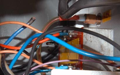
The SCR Controller, SCR Power Block, HV Transformer with current limiting resistor, HV rectifier diodes, charging and dump resistors, LED status lights, Trigger Inhibit boxes, and all control and coaxial cables that went to the main control rack were removed. These functions were replaced by a new dual charging board and two Gamma Power supplies as shown the right picture.

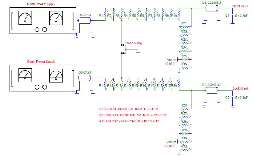
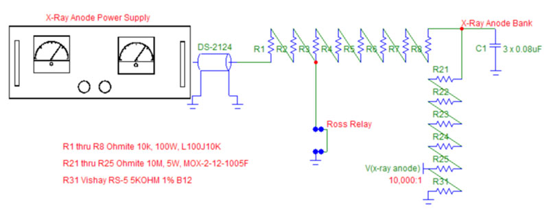
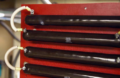
Each side of the dual charging board (see schematic on bottom of previous page) utilizes ten 10K, 100W Ohmite wirewound resistors that serve to isolate the Gamma power supplies and additionally provide energy dumps for both Thyratron Banks via the common Ross relay. Each charging side of the board is the same; only the North side will be described herein but the South side functions in the same manner. Resistors R3 through R10 are used to dump a maximum 675 joules of stored energy in the five 0.30 uF capacitors per bank when charged to 30 kV. Resistors R1 and R2 can be used to set the constant current charging current limit of the Gamma power supply when the Ross relay is left de-energized. Resistors R21 through R25 and monitor resistor R31 provide a 10,000:1 voltage divider to be terminated into 1 Megohms or greater for power supply calibration purposes. This divider is not resistor-capacitor compensated and is not intended to observe fast discharge pulses. The 50-Megohm-divider string also provides a slight bleed for the power supply to help hold the charge voltage accurately. The North and South Banks were made completely independent by removing the 3K, 250W Ohmite wirewound cross-connecting resistor and associated hardware in the top oil tank. The output of each new charging resistor string was connected to the North and South capacitor banks via a Dielectric Sciences coaxial, silicone based, semicon graded, high-voltage cable rated at 60 kV DC.

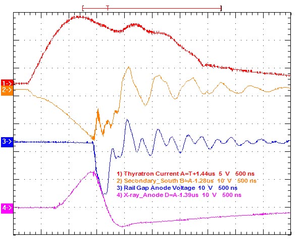
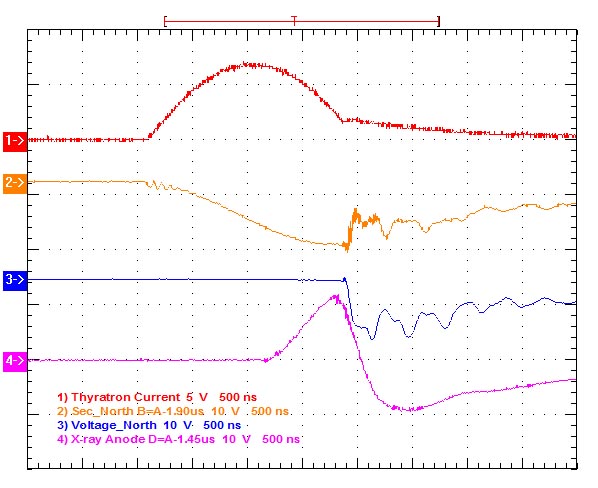
Both the North and South Banks were operated at a constant charging current of 12 ma and a charge voltage of 28 kV; this operation was successfully achieved only after much troubleshooting discussed later in this report. The constant current charging time can be estimated to be T = CV/I = (1.5uF)(28kV/(12ma) = 3.5 secs. In actuality, the charging time is a little greater due to the slight voltage drop across the charging resistor string as the power supply switches from constant current to constant voltage operation as the final charge voltage is reached. This power supply portion of Prometheus is only compatible with 0.2 Hz operations unless reduced power operations are invoked. The scope trace on the top of the next page shows the North and South Bank secondary voltages as well as the Thyratron primary currents.

Referring to the scope traces on the top of the next page, at first glance it appears that the transfer time of the North Bank (Red) appears to be faster than that of the South Bank (Blue) causing the Rail Gap switchout to be late by a few 100 ns for the North Bank. On the other hand, the North Thyratron primary current is slightly slower than that of the South. Both the North and South Thyratron secondary voltage traces start out somewhat different but are repeatable. The triggering of the North Thyratron Bank could be set to occur slightly later than the South Bank if so needed. The operation of the South Bank appears to be optimum. The flattening of the peak of the North Bank trace just before Rail Gap switchout is not seen on every trace; its cause is not explained at this time. The system was operated for about one hour at 0.2 Hz until a failure of the North Thyratron Bank occurred. The fault was traced to a single Thyratron on the North Bank and will be discussed in more detail later in this report.

Operational conditions for Prometheus at 28 kV (Full Power):
X-ray Anode Gamma Supply: 27 kV and 5 ma
North/South Gamma Supplies: 28 kV and 12 ma
Repetition Rate: 0.2 Hz
Maxwell 40168 Spark Gap Pressure: 35 psig
Maxwell 40161 Spark Gap Pressure: 64 psig
Maxwell Rail Gap Pressure: 34 psig

(Written by Randy Carlson)

Friday, June 23, 2006

Replaced X-ray Gun Anode Power Supply Successfully

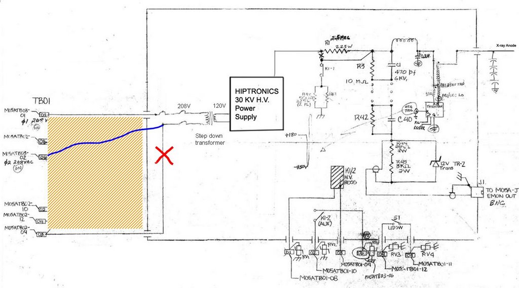
Compared the schematics of old X-ray anode, we replaced the Hiptronics 30kV 5mA power supply with GAMMA 40kV 15mA power supply.

Replace X-ray Anode Power Supply and Upgrade High Voltage Tank

The Hipotronics Power Supply and most all components in the X-ray Anode High Voltage Unit (M05A) were removed except those concerned with the operation of the Ross relay in the HV Tank. A better layout of the capacitors in the HV Tank improving and eliminating suspect connections, a lower inductance and more robust ground, and routing all cables through a slotted hole in the corner of the HV Tank lid were provided. The previous voltage monitor, charging resistors, and dump resistors were removed. These functions were replaced by components mounted on a Lexan board that can be easily removed if a failure occurs. These actions enable the lid to be secured during operation and, if necessary, readily removed for component inspection during operation. The HV Tank lid interlock was made active; it had been previously bypassed. A schematic of the new X-ray Anode HV Tank charging board is shown below and now discussed.The X-ray anode charging board utilizes eight 10K, 100W Ohmite wirewound resistors that serve to isolate the Gamma power supply and additionally provide an energy dump via the Ross relay. Resistors R3 through R8 are used to dump about 110 joules of stored energy in the three 0.08uF capacitors when charged to 30 kV. Resistors R1 and R2 can be used to set the constant current charging current limit of the Gamma power supply when the Ross relay is left de-energized. Resistors R21 through R25 and monitor resistor R31 provide a 10,000:1 voltage divider to be terminated into 1 Megohms or greater for power supply calibration purposes. This divider is not resistor-capacitor compensated and is not intended to observe fast discharge pulses. The 50-Megohm-divider string also provides a slight bleed for the power supply to help hold the charge voltage accurately.

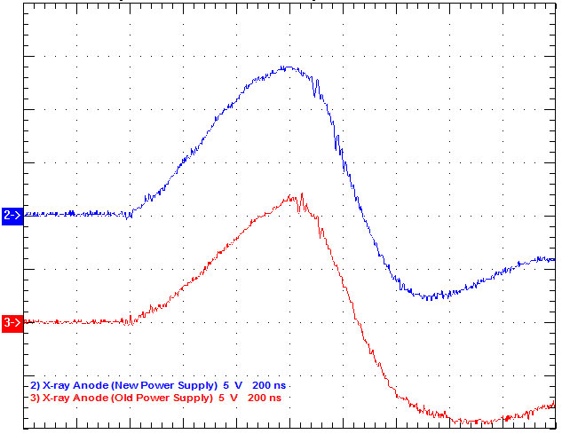
The X-ray Anode unit was operated at a constant charging current of 5 ma and a charge voltage of 27 kV giving a dose rate of about 0.4 mR/hr from the X-ray Anode electron source. The constant current charging time can be estimated to be T = CV/I = (0.24uF)(27kV)/(5ma) = 1.30 secs. In actuality, the charging time is a little greater due to the slight voltage drop across the charging resistor string as the power supply switches from constant current to constant voltage operation as the final charge voltage is reached. This power supply portion of Prometheus is compatible with 0.4 Hz operations. The scope trace as shown right picture compares the previous X-ray anode results with those of the new power supply system. The X-ray pulse is slightly higher and faster due to the lower inductance associated with a better layout and grounding of the capacitors in the X-ray Anode HV Tank.
(Written by Randy Carlson)

Thursday, June 22, 2006

Install Gamma High Voltage Power Supplies in Main Control Rack

In preparation for installing the three gamma power supplies in the main control rack, the diagnostics patch panel was moved to be at the top of the rack containing the two Tektronix 2024 scopes. The System Control Unit (R01), Gas Processor Control Unit (R04), and the Vacuum Gauge Controller Unit (R05) were moved toward the bottom of the main control rack. The High Voltage Control Unit (R03) was removed along with its associated shielded “gray cube” box that contained the previous Main Charging control electronics. All unused control and coaxial cables were removed between the main control rack, the Pulse Modulator HV Power Supply (M03), the X-ray Anode High Voltage Unit (M05A), and the X-ray Anode HV Tank (MO5B). Three Gamma power supplies were then mounted in the main control rack and additionally supported on rails. Although not necessary, a space of 1.75” was left between the power supplies for more than adequate cooling and ease of installation. The X-ray Anode Gamma power supply was connected to the X-ray Anode HV Tank via a 100-foot Dielectric Sciences (DS-2124) coaxial charging cable. This cable is polyethylene based with a graded semicon center shield robustly rated for 100 kV DC. The other two Gamma supplies were connected to a new dual charging board (described later) via similar 34-foot long coaxial cables. All three power supplies are supplied by 120 VAC power from three unused legs of the 208 three-phase Main Power Interconnect Box (M00). The power requirements of each supply are 7 amps at 120 VAC. Appropriate circuit breakers are now on hand and need to be installed in the future. The fourth Gamma power supply that had damaged current and voltage meters during shipment to UIC was repaired with parts from Gamma High Voltage Research and tested; this power supply should be used as a direct replacement spare.
(Written by Randy Carlson)

Wednesday, June 21, 2006

Install new H.V. power supply for X-ray Anode

Randy and John came to help us to install the new High Voltage power supply for x-ray anode. This will simplify the system.

When we tried to apply voltage up to 4kV, we found there was a big current leak. We traced the whole circuit including Thyratron, charging resistors, Ross relay and tranformer connectors. The problem is from the resistor plate, there was a screw hole, which was drilled very deep to cause an arcing when applied high voltage. Randy decided to replace them with the Nylon screws.

Thursday, June 08, 2006

Photonic Frontiers: Laser Acceleration: Short pulses speed particles

Intense femtosecond pulses can accelerate electrons, protons, and ions to high energies over very short distances, and could lead to a new class of compact, high-current accelerators.

Jeff Hecht, contributing editor

The concept of laser acceleration of charged particles dates back to 1979 when Toshi Tajima and John M. Dawson predicted that intense laser pulses could create a wake of plasma oscillations that could accelerate electrons to high energy.1 Their computer simulation of the effect attracted considerable interest because it held out the prospect of useful acceleration over much shorter distances than conventional particle accelerators. However, the short-pulse lasers of the day could not generate the peak powers needed for useful laser acceleration.

That changed with the development of chirped pulse amplification, which can generate extremely high peak powers in ultrashort pulses. The past several years have seen remarkable experimental progress, first with electrons and more recently with protons and heavier ions. Early experiments produced particles over a wide energy range, but recent results have narrowed the range of energies, a crucially important feature for applications that require precise control over particle energies.

Particle acceleration basics

Traditionally, charged particles have been accelerated by passing them through long metal tubes in which alternating electromagnetic fields were applied to a series of segments. The applied fields reverse as the particles pass through the segments, so the fields always accelerate the particles. The longer the tube, the more acceleration is applied to the particles, and the higher their energy. Laboratory-scale accelerators have meter-long tubes, but the accelerators used in cutting-edge high-energy physics can be several kilometers long. The maximum acceleration possible depends on the accelerator structure and the power of the alternating field. The upper limit is acceleration that increases energy by tens of megaelectronvolts per meter of tube length, so very high energies require huge accelerators.

Laser acceleration can generate much higher fields, so acceleration distance can be much shorter-typically a millimeter to drive electrons to 100 MeV. Firing powerful ultra-short pulses into a plasma or solid generates extremely intense electric fields, which can reach teravolts per meter at the instant of peak intensity. These fields overwhelm the electric attraction between the positive nucleus and the negative electrons, freeing both electrons and positive ions. The process also generates intense fields that accelerate the particles to high energies over short distances.

“Electron acceleration and proton acceleration are fundamentally different,” says Thomas Katsouleas of the University of Southern California (Los Angeles, CA), so different approaches have been developed for the two. The original laser-wake-field approach proposed by Tajima and Watson deposits energy in a plasma and works best for electrons. Protons and ions are much heavier and better accelerated by firing laser pulses that explode thin-film targets, freeing bursts of charged particles.

Laser-wake-field acceleration

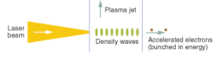
Wake-field acceleration is often compared with surfing. When an intense laser pulse hits a plasma, it creates a density wave of free electrons. The electrons, in turn pull positive ions-protons or heavier nuclei-along with them, creating a density wave as they pass through the plasma (see Fig. 1). The density wave carries the free electrons with it, and the electrons can reach 100-MeV energies within a millimeter, roughly 1/5000th the distance needed in a conventional accelerator.

Like catching an ocean wave to surf, coupling a laser pulse into a plasma is tricky, and the process took time to perfect. The first experiments showed very fast acceleration, but it took time to increase the number of accelerated electrons and focus them in a narrow beam. In 2002, researchers accelerated a burst of 100 million electrons that spread within an angle of only three degrees, but their energy diverged widely.2 That was a concern. “For a lot of applications it’s the ‘holy grail’ to get a monoenergetic beam,” Katsouleas says.

A major advance came in 2004, when three groups reported much narrower ranges of electron energy in papers that appeared in the same issue of Nature.3, 4, 5 The key to their success was finding ways to inject a clump of electrons into a small part of the plasma so the electrons can be accelerated collectively to nearly the same energy. The researchers fired pulses with peak powers of 10 to 30 TW and lengths of 30 to 55 fs into gas jets 2 mm long. By creating plasma channels or adjusting the laser beam to guide the density waves through the jets, they managed to constrain energy spread to no more than 24% for up to a few billion electrons (see Fig. 2).

Laser ion acceleration

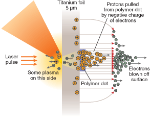
Protons and positive ions are too heavy for the wake-field approach to accelerate them effectively. Instead, researchers blow them away by hitting a thin, dense foil with a pulse reaching higher than 1018 W/cm2. The electric field is so much stronger than the nuclear attraction so it blows electrons out the back of the exploding foil at relativistic speeds. The electric charge of the accelerating electrons pulls protons or heavier ions along behind, accelerating the positive ions over micrometer-scale distances. “This is a pure one-stage process,” says Juan Fernandez of the Los Alamos National Laboratory (Los Alamos, NM).

Exploding foils were long known from inertial-confinement fusion experiments. However, they were not seriously considered for laser acceleration until the Lawrence Livermore National Laboratory (Livermore, CA) unexpectedly generated a well-controlled proton beam by firing its Petawatt laser at gold foils.6 Analysis showed that the protons came from impurities in the foil. The beam was intense, but ion energy was distributed over a wide range, and many applications require mono?energetic beams. Medical therapy, for instance, requires uniform energy to ensure the particles all penetrate the same depth.

A pair of experiments reported in January in Nature took a big step toward that goal, using different approaches to generate beams of protons and carbon ions with limited ranges of energy.

A team at Friedrich Schiller University (Jena, Germany) produced the proton beam by focusing 10-TW, 80-fs pulses from a Ti:sapphire laser to an intensity of 3 × 10¹⁹ W/cm2 on a 5-?m titanium foil. On the other side of the foil was an array of polymer dots 0.5 ?m thick and 20 ?m across. When a laser pulse hit the metal side of the foil behind a polymer dot, it blew off a cloud of hot electrons on the side of the dot, which in turn pulled protons from the polymer behind them (see Fig. 3). A plot of energy of the ?roughly 100 million laser-accelerated protons showed a narrow peak at 1.2 MeV, which was matched in simulations. The group calculates it could accelerate all 800 million protons in the polymer dot to an energy peak of 173 MeV-suitable for treating deep-seated tumors-if it had a laser that could deliver peak intensity of 10^21 W/cm^2.

Fernandez’s group at Los Alamos concentrated on the more difficult problem of accelerating heavier ions. It focused 30 TW, 600-fs pulses onto 10-um spots on a 20-um palladium foil with a thin graphite layer on the back. The intensity of 10^19 W/cm^2 blew relativistic ?electrons off the surface of the rear of the foil, which in turn accelerated highly ionized carbon atoms. The group found a 17% spread in the mean energy of about 36 MeV for the most abundant ions, C+5.

A key advantage of the laser approach is the ability to generate much higher ion currents than can conventional accelerators. Mutual repulsion of ions limits current in a conventional accelerator, but the laser accelerator can produce multiple kiloampere pulses because it produces a neutral beam containing electrons as well as ions, says Fernandez. “You’re shooting a plasmoid” that doesn’t want to fall apart.

Outlook

Laser accelerators are not going to replace the gigantic particle accelerators used in ?particle physics research. In principle, wake-field accelerators might be extended to produce high-energy electrons-but not protons. “You’re never going to make very high-energy proton beams this way,” says Fernandez.

But laser acceleration has two ?other big strengths. Because they use very intense fields to accelerate particles over short distances, they can be made small enough to fit in a laboratory, especially as the size of high-power, short-pulse laser comes down. Laser accelerators can also produce higher-?power beams. This combination makes them attractive for a wide range of applications. One is treating tumors with heavy ions, which deposit little energy until their velocity slows, zapping cancer cells deep inside the body without killing tissue along its path. Laser-accelerated beams might be used for fast ignition in inertial-confinement fusion. And once laser accelerators become available, more applications seem sure to appear.

REFERENCES

1. T. Tajima and J. M. Dawson, Phys. Rev. Lett. 43, 267 (July 23, 1979).
2. V. Malka et al., Science 298, 1996 (2002).
3. S.P.D. Mangles et al., Nature 431, 535 (Sept. 30, 2004).
4. C.G.R. Geddes et al., Nature 431, 538 (Sept. 30, 2004).
5. J. Faure et al., Nature 431, 541 (Sept. 30, 2004).
6. R. A. Snaveley et al., Phys. Rev. Lett. 85, 2945 (2000).
7. H. Schwoerer et al., Nature 439, 455 (Jan. 26, 2006).
8. B.M. Hegelich et al, Nature 439, 441 (Jan. 26, 2006).

Laser Focus World April, 2006
Tuesday, May 30, 2006

Mr. Beam Version 3.4.2-016
Bernd sent us the new version of MrBeam, it supports 3 different kinds of CCD camera.
a. LU 160 (wavefront sensor)
b. LU080 (beam stabilization)
c. LU160 (FROG).

Thursday, May 25, 2006

Boyer, Colgate awarded the 2006 Los Alamos Medal

Laboratory technical staff members Keith Boyer and Senior Laboratory Fellow Stirling Colgate, are recipients of the 2006 Los Alamos Medal. The Los Alamos Medal is the highest honor and most prestigious award the Laboratory can bestow upon an individual or small group. Director Bob Kuckuck will present the medals during a formal award ceremony and reception at 4 p.m. May 23, in the J. Robert Oppenheimer Study Center.

Recipients of the Los Alamos Medal are evaluated based on their exceptionally distinguished achievements that have impacted the success of the Laboratory, either through influencing mission accomplishments or enhancing distinction, making a contribution that changed the course of science and establishing a major direction for Los Alamos and/or the nation.

"Keith Boyer's and Stirling Colgate's distinguished careers at Los Alamos span more than four decades. Their contributions to Los Alamos and the nation have been immense and further underscore the vital importance this Laboratory has played in the past and the excellent science we continue to perform in support of the nation. I am honored and humbled to be able to present the 2006 Los Alamos Medal and I want to say to them, 'thank you for your contributions,' " said Director Bob Kuckuck.

Boyer has served the Laboratory for 55 years and is recognized as being the intellectual force behind Los Alamos’s entry into magnetic fusion, nuclear rocketry, laser isotope separation and inertial fusion. Boyer, who received his doctorate in nuclear physics from MIT, is credited with introducing and leading dramatic advances in science and engineering and has been involved in producing the first neutrons from a thermal plasma, co-inventing the electron beam carbon-dioxide laser and advancing x-ray lasers for high resolution microscopy. After retirement, he continued research and is responsible for a breakthrough in the development of an x-ray laser camera that promises to offer a nanoscale measurement technique comparable in importance to the development of the optical microscope. He is also recognized for his foresight in recruiting and nurturing excellent research people within the Laboratory.

“I was surprised and delighted to hear about my being awarded the Los Alamos Medal,” said Boyer. “I am particularly appreciative of the very generous support from my peers. I again feel that I am a member of Los Alamos Laboratory and have begun to think of new developments for the Laboratory.”

Colgate’s association with Los Alamos began when he was a student at the Los Alamos Ranch School until it was closed by the government in the early 1940s. He obtained his doctorate in physics from Cornell University and worked at Lawrence Livermore and New Mexico Institute of Mining and Technology. He joined the Laboratory in 1976 where he worked in the Theoretical (T) Division. He is recognized for leading the nuclear diagnostics of the nation’s largest weapons test conducted by Los Alamos, and for negotiating the cessation of high-altitude and outer space nuclear tests. Colgate also has inspired the inertial fusion and astrophysics programs at Los Alamos and Lawrence Livermore and contributed basic science to fusion ignition and burn, plasma confinement and shock wave physics. His other accomplishments include seminal work in supernovae and gamma ray bursts. Colgate is a recognized leader in recruiting leading weapons physicists and demonstrates by example that basic and applied science must be partners.

“So many people contribute to one’s career and this is especially true of a scientist,” said Colgate. “In serving two national labs and a state institution of learning I feel all those many people who have contributed to and encouraged me so much should feel associated with this honor.”

Colgate and Boyer join past Los Alamos Medal winners, Conrad Longmire, Nobel Laureate Hans Bethe, former Laboratory Director Harold Agnew, and Laboratory Fellows Nerses “Krik” Krikorian, George Cowan, Francis Harlow and Louis Rosen in this distinction.

(By Sallie Boorman)

Wednesday, May 17, 2006

Measuring the output energy

The timing delays of DG 535:
A=T+1.44us
B=A-1.28us
C=B+30ns
D=A-1.39us

The final output energy was measured about 350 mJ with the seed pulse energy 25 mJ.

Tuesday, May 16, 2006

X-ray Anode time delay adjustment

Randy suggested firing the X-ray Cathode and Anode slightly earlier. The previous delay time was set D=B-1.31us, in this condition the Rail Gap Anode firing was missed sometimes. When the firing time was moved forward, the Rail Gap firing became stable.

The Prometheus has been passivated for about 3 hours with the hight voltage of 10kV and DG 535 time delays of B=A-1.90us, D=A-1.45us. The red light was not changed anymore.

Monday, May 15, 2006

The Prometheus Passivation

Because the output energy of the Prometheus was too low, I decided to passivate it. The chamber was vacuumed this morning, then Helium gas was filled into the chamber about 1 bar. A 16kV H.V. pulse was applied to the rail gap. After filling several mbar fluorine gas, the emission light was changed from white to red. In order to make the railgap firing at the peak time of transformer secondary, I changed the SRS DG-535 channel B timing, from B=A-1.58us to B=A-2.20us. This status has been kept for one hour, then I found a spark on the top 10k Ohm charging resistor. I had to stop passivation, and found the resistor broken. What caused this happened?

Later I replaced the broken resistor, and tried to passivate the Prometheus again. I also measure the Thyratron currents at different timing delays(158us, 190us, 220us).

Friday, May 12, 2006

Cooling the Prometheus gases, ASE too low

The Prometheus ASE was very weak, so I decided to clean the gases by cooling recycle. After cooling, the ASE became bigger, however the ASE energy dropped fast after running for several minutes. The final amplified energy of the system is only about 100 mJ. I want to passivate the Prometheus next Monday to improve the ASE output.

Thursday, May 11, 2006

Cleaning the windows

I removed the windows of the long tube, and found some small black grains on the inside surface. I carefully cleaned the window and reinstalled them immediately. After that I passivted the both tube for about one and half hours, the long and short tubes emitted red light. Finally I measured energy of the TWIN excimer with 45 mJ, and the beam pattern looked better than before.

Wednesday, May 10, 2006

TWIN dirty windows

I tried to measure the laser energy, however I found the output energy of LLG-TWIN was very low. This seed beam could not be amplified up to ~500 mJ after passing the Prometheus. The pre-amplified beam patten looked very bad, I checked the windows and found they are very dirty. So I want to clean them tomorrow.

Tuesday, May 09, 2006

Testing the Eurothrem 7100A Thyristor Controller

Introduction:

The Eurothrem 7100A Thyristor controller is intended to replace the Eratron SCR controller in the Prometheus laser.The Eurotherm units are speced at 100A 230/240V service with a 5 V analog control input signal.

Breadboard:


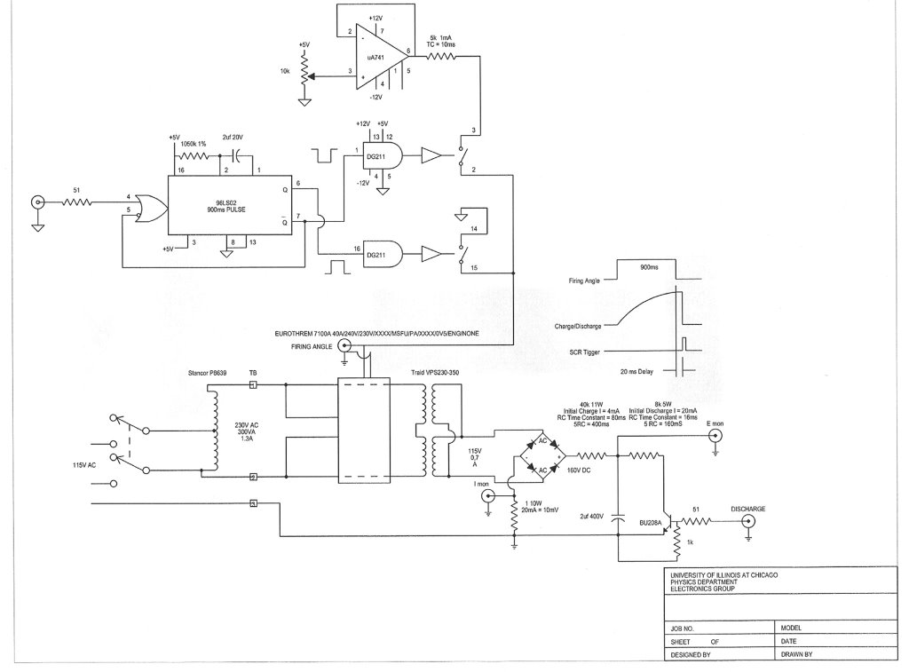
The following circuit was breadboarded to test the Eurotherms. A Stanford Research Instrument Delay Generator is use for timing the firing of the Eurothrem and the discharging of the holding capacitor.
Rep Rate 0.2Hz
Delays
A = T+0
B = T+50ms
C = T+1.2s
D = T+1.3s
AB triggers the 900ms flip/flop gating the analog signal to the Eutotherm. CD gates the discharge transistor. The control level is adjustable form 0 to 5V. The full wave bridge output voltage is ~ 160VDC.

Analysis:

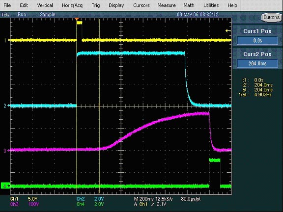
The oscilloscope traces shows a built in time delay of ~ 200ms between the rising edge of the control signal input and the firing of the thyristors. If the Eurothrem units are used the 200ms delay will have to figured into the system timing.
Yellow = AB Trigger monitored at F/F input
Blue = Analog Control Signal monitored at Eurotherm input
Violet = E Charge Curve monitored on the holding capacitor
Green = Discharge Signal monitored at the Discharge input
(Written by Michael F. Klawitter)

Monday, May 08, 2006

Trigger channels changed

I tried to trigger channel B (M02) of DG-535 firstly using the SDG II TRIG OUT signal and set up the other channels as below:
A=B+1.57 us
B=T+30 ns
C=B+30 ns
D=B+1.3 us
Under this setup, the laser pulse output is same as the last Friday.

Friday, May 05, 2006

The system timing adjustment

Usually we sent the SYNC OUT signal from SDG II to trigger the Prometheus, it would induce about several hundreds nanoseconds delay time. Today I changed this signal from SYNC OUT to TRIG OUT. Finally I could match the seed beam with the Prometheus ASE.

Timing setup:

SDGII: OUT1=188ns, OUT2=368ns, SYNC OUT=204ns

DG535: A=T+1.60us (Rail Gap), B=A-1.54us (M02), C=B+30ns (M01), D=A-1.31us (X-ray Anode).

Wednesday, May 03, 2006

Jitter of laser pulse

I set the Thyratron heater and reservoir voltages back to 10.06V and 8.17V. In order to avoid the acring, I inserted a plastic plate between the thyratron and ground plate.

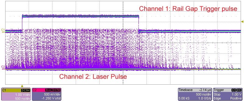
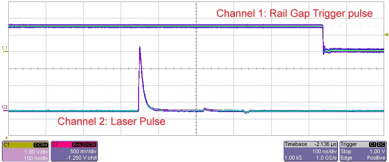
In the afternoon, I tried to send the TWIN laser pulse to the Prometheus. Firstly I wanted to use the method of the first pulse triggered and the second pulse amplified. However, it's very difficult to match these two pulses, I thought there was a time jitter between them. The 4 channels of DG-353 were set as: A=T+250ms 212us 236ns (Rail Gap), B=A-1.66us (M02), C=B+30ns (M02), D=A-1.42us (X-ray Anode). I used a fast photo diode to measure the laser pulse and compared it with the Prometheus trigger signals. From the measurement, I found the laser pulse jitter was more than 2.0us, which might cause the failure of two pulses matching.

Then I used only one pulse to trigger the Promethus and to be amplified. The channel A of DG-535 was changed to A=T+1.71us, and the rest channels were set as above. Please notice the time division, the above is 500ns/div, this one is 100ns/div, the tracing time is same. The jitter time is less than several nanoseconds, that's enough for matching the Prometheus pulse.

However, the time delay of 1.71us was still big, the Prometheus should be triggered early a little bit (about 0.25us). Because the Thyratron (M01&M02) would be triggered early 1.66us than the Rail Gap, it means the Rail Gap delay time must be set more than 1.66us. If we want the pulses matching, the A channel should be set A=T+1.46us. I need time to consider the whole system timing.

Tuesday, May 02, 2006

The TWIN system running well

I removed the bad connector of the heater, and reconnected them. The TWIN system ran pretty good. However I found there were the arcing around the Thyratron and the ground plate, this is a small problem, I will put a plastic plate between them or tighten them.

Monday, May 01, 2006

Wire Broken

I open the TWIN chamber this afternoon, and found the wire connected to reservoir voltage was broken. I think it might cause the TWIN not running. I will repair the wire tomorrow. The filter connector was not well when we repaired the TWIN on Oct. 20, 2005.

Changing Heater and Reservoir Voltages for TWIN Thyratron

I adjusted the heater voltage and reservoir voltage. These voltages were set at 10.06 VAC(Heater) and 8.04 VAC (Reservoir) respectively. In the beginning, I turn on the system after 10 or 15 minutes warming up, the TWIN ran at 5 Hz for 1 second, then the repetition rate changed to 1 Hz, after 2 or 3 shoots, there was no operation anymore. I increased the V_H to 10.71 VAC, V_R to 8.35 VAC the TWIN did not run. When I increased the V_R up to 8.77 VAC, the TWIN was interlocked as soon as I turn on.

I have to shut down the TWIN system. Several minutes later, I turn on the system and warmed up, set the V_H 11.38 VAC, V_R 8.40 VAC, the repetition rate 5Hz. This time the TWIN ran normally, then I increased the repetition rate to 6Hz, everything was ok! Then turn off the system, set the repetition rate up to 8 Hz, the TWIN was not running, after a few seconds, it ran at low rate then up to 8 Hz. After the system ran for a couple minutes, I turn it off again and increased the repetition rate up to 10Hz, this time the TWIN ran normally after 1 minute. However, when I decreased the rate down to 5 Hz, the TWIN was dead again.

I have to shut down the TWIN again and left it not run for a couple of minutes. Then I set up the V_H 11.35VAC, V_R 8.35VAC, the TWIN has been run well for about 30 minutes. Then the TWIN excimer became unstable, there were one miss fire after 10 shoots (@repetition rate 10Hz). I switched off the TWIN and waited for several minutes, then turn it on, but just run 1 minutes, the TWIN became unstable either at 5Hz or 10Hz.

I found the TWIN excimer was sensitive to the reservoir voltages, when V_R under 8.35 VAC, the TWIN could be run; when the reservoir value up to 8.35 VAC, the power supply would be interlocked. I don't know why.