Replace X-ray Anode Power Supply and Upgrade High Voltage Tank
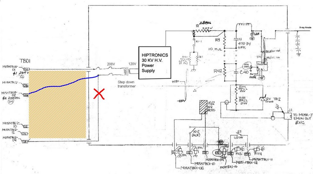
The Hipotronics Power Supply and most all components in the X-ray Anode High Voltage Unit (M05A) were removed except those concerned with the operation of the Ross relay in the HV Tank. A better layout of the capacitors in the HV Tank improving and eliminating suspect connections, a lower inductance and more robust ground, and routing all cables through a slotted hole in the corner of the HV Tank lid were provided. The previous voltage monitor, charging resistors, and dump resistors were removed. These functions were replaced by components mounted on a Lexan board that can be easily removed if a failure occurs. These actions enable the lid to be secured during operation and, if necessary, readily removed for component inspection during operation. The HV Tank lid interlock was made active; it had been previously bypassed. A schematic of the new X-ray Anode HV Tank charging board is shown below and now discussed.
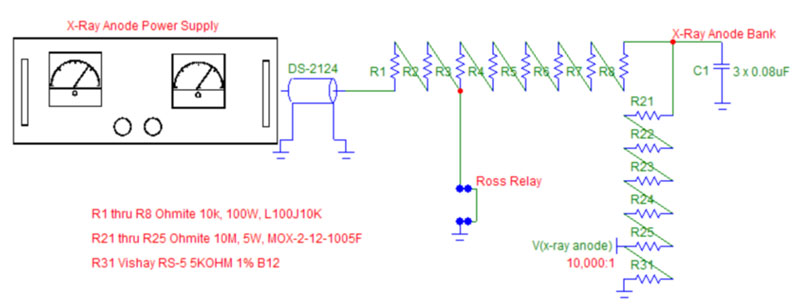 The X-ray anode charging board utilizes eight 10K, 100W Ohmite wirewound resistors that serve to isolate the Gamma power supply and additionally provide an energy dump via the Ross relay. Resistors R3 through R8 are used to dump about 110 joules of stored energy in the three 0.08uF capacitors when charged to 30 kV. Resistors R1 and R2 can be used to set the constant current charging current limit of the Gamma power supply when the Ross relay is left de-energized. Resistors R21 through R25 and monitor resistor R31 provide a 10,000:1 voltage divider to be terminated into 1 Megohms or greater for power supply calibration purposes. This divider is not resistor-capacitor compensated and is not intended to observe fast discharge pulses. The 50-Megohm-divider string also provides a slight bleed for the power supply to help hold the charge voltage accurately.
 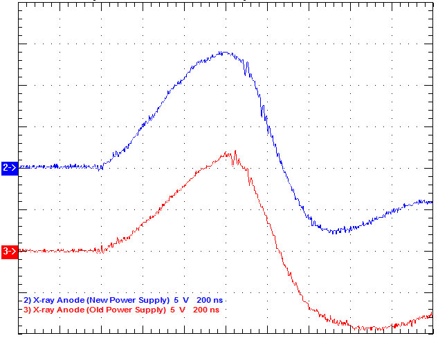 The X-ray Anode unit was operated at a constant charging current of 5 ma and a charge voltage of 27 kV giving a dose rate of about 0.4 mR/hr from the X-ray Anode electron source. The constant current charging time can be estimated to be T = CV/I = (0.24uF)(27kV)/(5ma) = 1.30 secs. In actuality, the charging time is a little greater due to the slight voltage drop across the charging resistor string as the power supply switches from constant current to constant voltage operation as the final charge voltage is reached. This power supply portion of Prometheus is compatible with 0.4 Hz operations. The scope trace as shown right picture compares the previous X-ray anode results with those of the new power supply system. The X-ray pulse is slightly higher and faster due to the lower inductance associated with a better layout and grounding of the capacitors in the X-ray Anode HV Tank.
(Written by Randy Carlson)
No comments:
Post a Comment