 The SCR Controller, SCR Power Block, HV Transformer with current limiting resistor, HV rectifier diodes, charging and dump resistors, LED status lights, Trigger Inhibit boxes, and all control and coaxial cables that went to the main control rack were removed. These functions were replaced by a new dual charging board and two Gamma Power supplies as shown the right picture.
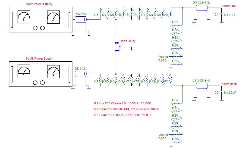
Each side of the dual charging board (see schematic on bottom of previous page) utilizes ten 10K, 100W Ohmite wirewound resistors that serve to isolate the Gamma power supplies and additionally provide energy dumps for both Thyratron Banks via the common Ross relay. Each charging side of the board is the same; only the North side will be described herein but the South side functions in the same manner. Resistors R3 through R10 are used to dump a maximum 675 joules of stored energy in the five 0.30 uF capacitors per bank when charged to 30 kV. Resistors R1 and R2 can be used to set the constant current charging current limit of the Gamma power supply when the Ross relay is left de-energized. Resistors R21 through R25 and monitor resistor R31 provide a 10,000:1 voltage divider to be terminated into 1 Megohms or greater for power supply calibration purposes. This divider is not resistor-capacitor compensated and is not intended to observe fast discharge pulses. The 50-Megohm-divider string also provides a slight bleed for the power supply to help hold the charge voltage accurately. The North and South Banks were made completely independent by removing the 3K, 250W Ohmite wirewound cross-connecting resistor and associated hardware in the top oil tank. The output of each new charging resistor string was connected to the North and South capacitor banks via a Dielectric Sciences coaxial, silicone based, semicon graded, high-voltage cable rated at 60 kV DC.
Both the North and South Banks were operated at a constant charging current of 12 ma and a charge voltage of 28 kV; this operation was successfully achieved only after much troubleshooting discussed later in this report. The constant current charging time can be estimated to be T = CV/I = (1.5uF)(28kV/(12ma) = 3.5 secs. In actuality, the charging time is a little greater due to the slight voltage drop across the charging resistor string as the power supply switches from constant current to constant voltage operation as the final charge voltage is reached. This power supply portion of Prometheus is only compatible with 0.2 Hz operations unless reduced power operations are invoked. The scope trace on the top of the next page shows the North and South Bank secondary voltages as well as the Thyratron primary currents.
Referring to the scope traces on the top of the next page, at first glance it appears that the transfer time of the North Bank (Red) appears to be faster than that of the South Bank (Blue) causing the Rail Gap switchout to be late by a few 100 ns for the North Bank. On the other hand, the North Thyratron primary current is slightly slower than that of the South. Both the North and South Thyratron secondary voltage traces start out somewhat different but are repeatable. The triggering of the North Thyratron Bank could be set to occur slightly later than the South Bank if so needed. The operation of the South Bank appears to be optimum. The flattening of the peak of the North Bank trace just before Rail Gap switchout is not seen on every trace; its cause is not explained at this time. The system was operated for about one hour at 0.2 Hz until a failure of the North Thyratron Bank occurred. The fault was traced to a single Thyratron on the North Bank and will be discussed in more detail later in this report.
Operational conditions for Prometheus at 28 kV (Full Power):
X-ray Anode Gamma Supply: 27 kV and 5 ma
North/South Gamma Supplies: 28 kV and 12 ma
Repetition Rate: 0.2 Hz
Maxwell 40168 Spark Gap Pressure: 35 psig
Maxwell 40161 Spark Gap Pressure: 64 psig
Maxwell Rail Gap Pressure: 34 psig
(Written by Randy Carlson)
No comments:
Post a Comment