Friday, July 21, 2006
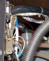
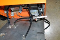
Changed the H.V. cable
I found a spare cable in the lab, so I just replaced the burnt cable with it. But the plug body connected with the power supply was borken, so I replaced it with the plug body of the burnt cable.
Wednesday, July 19, 2006
TWIN H.V. cable burnt
 In the afternoon, the TWIN excimer amplifier suddenly stopped firing after running for half hour. I found the power supply light became red, the light was off after pressing the reset button. Then I pushed the H.V. button and Laser button, I heard a buzz sound inside the excimer chamber. I energized gradually to the amplifier, the voltage reached 12 kV, the buzz appeared again then the system shut down immediately.
I opened the chamber, and turn on the system to check where the buzz came from. I found the high voltage cable was burn, the buzz was from the broken cable. The arcing from the cable caused the fail in high voltage increasement.
Tuesday, July 18, 2006
Arcing from LLG-TWIN excimer inside
 When I ran the TWIN excimer amplifier, I could hear the crack sound inside the chamber. This phenomenon was happened before, which was caused by the spark from the Thyratron plate and ground plate. I put two picece of plastic sheet to isolate them. Probably the sheet became dirty or they were too thin. The Thyratron plate should be tightened with the real ground plate in order to avoid the spark, however it will take several days to remove the plate to drill the holes for tightening. The simple way is to replace the isolating plate with a new teflon plate. After replacing, the system ran well.
Friday, July 07, 2006
Modification of front end timing
 In order to synchronize the seed pulse and Prometheus ASE, I tried many ways without using more delay control equipments. But all the attempts were failed, I have to consider change the front end timing. By studying the old system timing, I found a 10ms delay was added to the CAP pump Q-switch laser, I could copy this setup for our new system. So I inserted a 1ms delay by using BNC delay controller, then replaced the original delay controller from LLG with SRS DG-535. The channel A of DG-535 was used to switch Pockell in and channel C for Pockell switch out. The output of channel D was used to control the excimer control box.
We will have extra 1 ms time delay for the Prometheus trigger and target nozzle controller.
Wednesday, July 05, 2006
Overlapping seed beam and Prometheus ASE
 I tried to match the seed laser beam and the Prometheus ASE. The Prometheus ran in the good condition when Thyratron trigger and X-ray Anode trigger was set by 1.78 us and 1.22us earlier than Railgap trigger respectively. So the time delay between seed pulse and Prometheus could not be set less than 1.78us. I tried to adjust the time delay from 1.8us to 1.5 us (as shown in the pictures). I found when time delay was 1.5us, two pulses were overlapped, but the thyratron current wave forms indicated the Thyratron had no time to totally turn off.
The best solution is to add an extra time delay in the front end.
Monday, July 03, 2006
Timing Diagram
 We simplified the timing setup when we installed the new High Voltage power supply. The prevent circuit has been removed, the Thyratrons were triggered directly by the signal pulses from SRS DG-535. The repetition rate was decreased by 0.2 Hz for Prometheus, the 4 channels were set as A=T+1 ms, B=A-1.75 us, C=B+30 ns, D=A-1.21 us.
Subscribe to:
Comments (Atom)

