Wednesday, January 31, 2007
Passivating the Protmehtes
Last week, we removed the Prometheus windows for cleaning. At the same time, we cleaned the 40168 spark gap at Rail Gap Trigger Unit. Unfortunately, the pipe fittings for spark gap were broken, we had to order them. This caused us to wait for about 2 days. Now everything is already, we are going to passivate the Prometheus. The operating voltage was about 14 kV for each bank, the passivation kept about 2 hours.


Friday, January 19, 2007
Labview blcok for SDG II control box
Most functions of the SDG II can be controlled by any computer with a standard RS-232 serial port. After connecting the SDG II with computer RS-232 through data transmission cable, it's easy to control the SDG II by sending a RS-232 commands. Valid commands return the string "Ok", but invalid commands or queries return the string "Bad".
 I can run a program under Labview to send or query RS-232 commands only by pushing buttons. The front control panel and LabView block diagram are shown here.

 I can run a program under Labview to send or query RS-232 commands only by pushing buttons. The front control panel and LabView block diagram are shown here.
Wednesday, January 17, 2007
Set up timing delay for new designed nozzle
In order to synchronize the old small nozzle with laser pulses, I have added about 1 millisecond delay between the laser seed pulses and the final laser pulses. However, this delay is not enough for the new big slit nozzle, which needs at least 3 or 4 milliseconds to be operated. So I think it's better to trigger the nozzle with the first laser pulse and fire with the second laser pulse. Because the Prometheus runs at 0.2 Hz, there is 5 seconds delay between two continuous pulses. It's free to tune the delay time during this 5 seconds, the main point is how to synchronize the gas nozzle with the second laser pulse. A digital delay box was used, this box can provide the timing delay from seconds order to microsecond order. After several trials, the delay was set up at about 4 s 913 ms.
Wednesday, January 10, 2007
Changed resistors for 40184 spark gap
 I found the resistors connected to the 40184 spark gap was broken, which caused the misfire for the Prometheus. This 40184 spark gap(SG1) was installed inside the 50kV trigger generator box. SG1 is a three electrode, 2:1 gap-space, irradiated-gas-plasma switch. The switch operates in the swinging cascade mode in which the intermediate electrode is biased at one-third of the working voltage.
Wednesday, January 03, 2007
Testing NI GPIB-232CV-A
We received the National Instruments GPIB-232CV-A today, I installed the converter and tested it. The interesting thing was that I could use the mouse or keyboard plug, rather than a AC/DC power supply to provide the power for this board.
In order to make sure the board worked, I connect a TDS2042 oscilloscope with GPIB cable to the converter. Before testing, it's necessary to configure the converter parameters. The DIP switches were used to set up the parameters, the setup of SW1 was shown as followed:
The setup of DIP switch SW2 was shown as below:
After several times to change the DIP switches setup, the scope data was successfully transfered to the computer through scope GPIB port, converter and serial port.
In order to make sure the board worked, I connect a TDS2042 oscilloscope with GPIB cable to the converter. Before testing, it's necessary to configure the converter parameters. The DIP switches were used to set up the parameters, the setup of SW1 was shown as followed:
Indication | GPIB address | Termination | Mode | |||||
| Switches | 1 | 2 | 3 | 4 | 5 | 6 | 7 | 8 |
| ON/OFF | OFF | OFF | OFF | ON | OFF | OFF | ON | ON |
| Note | This address matched the scope GPIB address | LF termination | C | |||||
The setup of DIP switch SW2 was shown as below:
Indication | bits per second | Parity | Check | Stop | Data | Flow | ||
Switches | 1 | 2 | 3 | 4 | 5 | 6 | 7 | 8 |
ON/OFF | ON | OFF | ON | OFF | OFF | OFF | ON | OFF |
Note | 9600 baud | Odd | Disable | 1 bit | 8 | Disable | ||
After several times to change the DIP switches setup, the scope data was successfully transfered to the computer through scope GPIB port, converter and serial port.
Tuesday, December 19, 2006
Filaments and self-focusing of UV laser beam
 Yesterday we found the small mirror surface of the beam expander was damaged, we figured out that it was caused by the laser beam filament or self-focusing. We improved the spatial filter vacuum, covered the optical tables, cleaned the windows, and filled the new gases into TWINAMP. All these behaviors might increase the laser output energy, which finally provoked the strong nonlinear effect such as filament or self-focusing.
We used the photo papers to imprint the laser beam patterns, one was put before the beam expander, the other one was put in front of the convex mirror in the beam expander box. Each print recorded about 300 laser shots at ~24 mJ. It's obvious that the beam print before the telescope was smoother than the one in front of the convex mirror. Some dark spots were recorded at the edge or in the bottom of the laser beam, which almost matched the damaged spots on the convex mirror.
Wednesday, December 13, 2006
Beam Profiles of Tripler and after 1st sptial filter
 We measured the beam profile and wavefront of tripler (see the right figure). M2(X)= 1.58, M2(Y)=1.56; Beam width(X)= 3.3 mm, Beam width(Y)= 2.9 mm.
After the first beam expander, the beam size was enlarged about 10 times. In order to measure the whole beam, we used a lens to concentrated the beam into the CCD camera. The beam profile is shown in the below. Only the beam size was changed to bigger, the other beam characteristics were similar to the tripler one(see the bottom figure).

M2(X)=1.89, M2(Y)=1.72; Beam width(X)=20.5 mm, Beam width (Y) = 23.4 mm.
X-Ray Rainbow
via Physics News Update #805
 In 1670 Isaac Newton demonstrated the composite nature of sunlight when he sent a carefully collimated sunbeam through a prism, which spread out the light into a rainbow of colors; by sending a beam of single color through a second prism (with no further spreading) Newton showed that the color was not being imposed by the prism but was intrinsic to the light itself. Now physicists using the Advanced Photon Source at Argonne National Lab, in Illinois, have spread out a beam of X-rays (which are, after all, just a more energetic version of visible light) into a rainbow of colors.
Trying to reflect X-rays from a surface is difficult because X-ray wavelengths are some 10,000 times shorter than those for visible light. Glancing reflection of only a few tenths of a degree is normally possible, and even then the beam of X-rays will suffer very little wavelength-dependent spreading. However, another phenomenon, Bragg diffraction, allows for scattering of X-rays from a crystal through large angles; in this case the incoming X-rays scatter not merely from a top layer of atoms in the crystal but from numerous atomic planes. Furthermore, if the atomic planes are not parallel to the crystal surface the diffracted X-ray beam will be spread out prismatically into a range of component wavelengths (or colors).
In the Argonne experiment an incoming beam of 9-kiloelectronvolt X-ray photons with angular spread of only 1 micro-radian (two-tenths of an arcsecond) was backwards scattered and spread out into an X-ray rainbow with an angular dispersion of 230 micro-radians (see figure).
Argonne physicist Yuri Shvyd'ko (shvydko@aps.anl.gov, 630-252-2901) says that his rainbow is not just a novelty but will have many practical applications in X-ray optics. These include compression of X-ray pulses in time and the development of X-ray monochomators (which fashion X-ray beams of pure wavelength, or color) and much higher-resolution X-ray spectrometers.
Shvyd'ko et al., Physical Review Letters, 8 December 2006
 In 1670 Isaac Newton demonstrated the composite nature of sunlight when he sent a carefully collimated sunbeam through a prism, which spread out the light into a rainbow of colors; by sending a beam of single color through a second prism (with no further spreading) Newton showed that the color was not being imposed by the prism but was intrinsic to the light itself. Now physicists using the Advanced Photon Source at Argonne National Lab, in Illinois, have spread out a beam of X-rays (which are, after all, just a more energetic version of visible light) into a rainbow of colors.
Trying to reflect X-rays from a surface is difficult because X-ray wavelengths are some 10,000 times shorter than those for visible light. Glancing reflection of only a few tenths of a degree is normally possible, and even then the beam of X-rays will suffer very little wavelength-dependent spreading. However, another phenomenon, Bragg diffraction, allows for scattering of X-rays from a crystal through large angles; in this case the incoming X-rays scatter not merely from a top layer of atoms in the crystal but from numerous atomic planes. Furthermore, if the atomic planes are not parallel to the crystal surface the diffracted X-ray beam will be spread out prismatically into a range of component wavelengths (or colors).
In the Argonne experiment an incoming beam of 9-kiloelectronvolt X-ray photons with angular spread of only 1 micro-radian (two-tenths of an arcsecond) was backwards scattered and spread out into an X-ray rainbow with an angular dispersion of 230 micro-radians (see figure).
Argonne physicist Yuri Shvyd'ko (shvydko@aps.anl.gov, 630-252-2901) says that his rainbow is not just a novelty but will have many practical applications in X-ray optics. These include compression of X-ray pulses in time and the development of X-ray monochomators (which fashion X-ray beams of pure wavelength, or color) and much higher-resolution X-ray spectrometers.
Shvyd'ko et al., Physical Review Letters, 8 December 2006
Tuesday, December 12, 2006
1st Spatial Filter leakage
Mike helped us fix the vacuum pump for the first Spatial Filter of TWINAMP, however we found there was a big leak from the vacuum pipes. We checked the pipes step by step, firstly found one of the O-ring was broken, then small holes around the vacuum pipes. After replacing the O-ring and gluing the leaks, the vacuum reached about 10 mTorrs.
Monday, December 11, 2006
Supervision software operates and maintains large laser systems
I dreamed I could control the large laser system by computer someday, fortunately I found the Thales Laser company already achieved it.
Supervision software operates and maintains large laser systems
Auther: Fabien Ghez
Large laser systems, such as terawatt- and petawatt-class ultrafast amplifiers or Nd:glass fusion beams, are complex to use and maintain, primarily because they are large systems that comprise several smaller ones. A terawatt ultrafast laser, for instance, consists of several optical elements such as an oscillator and its pump, a set of amplifiers, many pump lasers, beam-shaping devices, a stretcher-compressor pair, timing electronics, cooling units, and systems that interface to user experiments.
So in addition to operating the overall system, a user must also bring a capacity for tuning and maintaining all of the components individually and collectively. Laboratories often employ engineers or Ph.D. scientists whose sole or primary responsibility consists of maintaining and operating such highly complex experimental tools. To ease this burden for the average user while enabling broader application of large laser systems, computerized supervision tools have become available that combine hardware and software dedicated to system operation, tuning, and maintenance. The goal of such processing capabilities, of course, is to enable the user to spend time on the application rather than on tweaking the laser. The primary processing tasks can be divided into two areas.
The first of these areas, synchronizing laser pulses of femtosecond duration to single-shot experiments with negligible jitter, is one of the toughest tasks in laser-driven experiments. Supervision software enables the laser to be slaved to external clock references, or to be used as a main system clock. In both cases computer-driven synchronization signals set the pace for both the laser and the experiments. X-ray generation in connection with a linear electron accelerator offers a classic example of this sort of application: the laser beam collides with an electron beam and subpicosecond accuracy is required despite the very noisy environment.
In terms of the second control area, laser operation and maintenance, supervision software and hardware enable automated start-up of all pumps and other devices, monitors operation of all systems, including motors and beam analyzers, and diagnosis malfunctions, thus enabling rapid preventive maintenance while minimizing the need for system tweaking. If a large laser system must operate in an environment that would be unsafe for human operators, such as a room exposed to harmful radiation, supervision software enables remote control of operational tasks such as start-up, shutdown, the control of energy levels, and the optimization and alignment the beam, all through a fiberoptic link.
System architecture
 In the Thales laser-control architecture, supervision software controls, through an RS232 connection, a laser-control system that drives all individual control units and drivers; a femtocontrol unit that drives the diagnostics; one or several synchronization units, CCD cameras and diagnostics; and all connections between computers, power supplies, electronic racks, and breadboards (see Figure).
The masterclock (synchronization unit) generates all signals to trigger pump lasers, Pockels cell, and CCD cameras in synchronization with the master RF of the oscillator. This provides the aforementioned system synchronization with the laser oscillator, reduction of jitter, and improvement of stability, whether within one laser system or among several. Of course, if the laser is only one part of a global facility, the computer can be linked to global supervision software via network connections and protocols to be determined by the user.
The femtocontrol unit is a single electronic rack that can simultaneously drive and control stepper motors, motorized mounts (x and y axis), and pump-laser interlocks. It can also make some spectral and power measurements using integrated photodiodes. Those integrated and calibrated photodiodes can be implemented in breadboards to control the power levels of different amplifiers and pump lasers.
The compressor can also be adjusted through the software, enabling pulse duration to be adjusted remotely without removing system covers (which can prove particularly useful with vacuum-chamber compressor systems, or pulse propagation in air). The software adjusts the distance between gratings by means of a translation stage.
The laser-beam profile can be monitored by the user on the computer screen through a Firewire CCD camera, which enables saving of the profile in jpeg format. This camera also enables control of beam profiles in intermediate amplifiers. And when coupled with an alignment system it can also control beam pointing.
In some experiments, precise pulse energy is required to improve efficiency. This can be achieved via an attenuation process that reduces output power without degrading other performance parameters (such as polarization, beam focusing, energy, stability, and contrast). The easiest way to implement such a solution is to modify the delay on pump lasers to reduce the gain of some amplifiers. The drawbacks of this solution are that it can degrade some parameters of the beam in a way that invalidates the experiments, and that a precise attenuation within the required range may not be possible. An alternative software-enabled solution avoids such problems by using rotating waveplates coupled to polarizers that can vary the output power from 15% to 100% without affecting other specifications.
The Thales supervision software is based on Labview 7.0 (National Instruments; Austin, TX), which in addition to user-friendliness enables compatibility with a broad range of user software systems. So when laser and experimental protocols are compatible it may even become possible to integrate laser control with experimental software, and to operate the laser and experiment as a single system.
From Laser Focus World November, 2006
Supervision software operates and maintains large laser systems
Auther: Fabien Ghez
Large laser systems, such as terawatt- and petawatt-class ultrafast amplifiers or Nd:glass fusion beams, are complex to use and maintain, primarily because they are large systems that comprise several smaller ones. A terawatt ultrafast laser, for instance, consists of several optical elements such as an oscillator and its pump, a set of amplifiers, many pump lasers, beam-shaping devices, a stretcher-compressor pair, timing electronics, cooling units, and systems that interface to user experiments.
So in addition to operating the overall system, a user must also bring a capacity for tuning and maintaining all of the components individually and collectively. Laboratories often employ engineers or Ph.D. scientists whose sole or primary responsibility consists of maintaining and operating such highly complex experimental tools. To ease this burden for the average user while enabling broader application of large laser systems, computerized supervision tools have become available that combine hardware and software dedicated to system operation, tuning, and maintenance. The goal of such processing capabilities, of course, is to enable the user to spend time on the application rather than on tweaking the laser. The primary processing tasks can be divided into two areas.
The first of these areas, synchronizing laser pulses of femtosecond duration to single-shot experiments with negligible jitter, is one of the toughest tasks in laser-driven experiments. Supervision software enables the laser to be slaved to external clock references, or to be used as a main system clock. In both cases computer-driven synchronization signals set the pace for both the laser and the experiments. X-ray generation in connection with a linear electron accelerator offers a classic example of this sort of application: the laser beam collides with an electron beam and subpicosecond accuracy is required despite the very noisy environment.
In terms of the second control area, laser operation and maintenance, supervision software and hardware enable automated start-up of all pumps and other devices, monitors operation of all systems, including motors and beam analyzers, and diagnosis malfunctions, thus enabling rapid preventive maintenance while minimizing the need for system tweaking. If a large laser system must operate in an environment that would be unsafe for human operators, such as a room exposed to harmful radiation, supervision software enables remote control of operational tasks such as start-up, shutdown, the control of energy levels, and the optimization and alignment the beam, all through a fiberoptic link.
System architecture
 In the Thales laser-control architecture, supervision software controls, through an RS232 connection, a laser-control system that drives all individual control units and drivers; a femtocontrol unit that drives the diagnostics; one or several synchronization units, CCD cameras and diagnostics; and all connections between computers, power supplies, electronic racks, and breadboards (see Figure).
The masterclock (synchronization unit) generates all signals to trigger pump lasers, Pockels cell, and CCD cameras in synchronization with the master RF of the oscillator. This provides the aforementioned system synchronization with the laser oscillator, reduction of jitter, and improvement of stability, whether within one laser system or among several. Of course, if the laser is only one part of a global facility, the computer can be linked to global supervision software via network connections and protocols to be determined by the user.
The femtocontrol unit is a single electronic rack that can simultaneously drive and control stepper motors, motorized mounts (x and y axis), and pump-laser interlocks. It can also make some spectral and power measurements using integrated photodiodes. Those integrated and calibrated photodiodes can be implemented in breadboards to control the power levels of different amplifiers and pump lasers.
The compressor can also be adjusted through the software, enabling pulse duration to be adjusted remotely without removing system covers (which can prove particularly useful with vacuum-chamber compressor systems, or pulse propagation in air). The software adjusts the distance between gratings by means of a translation stage.
The laser-beam profile can be monitored by the user on the computer screen through a Firewire CCD camera, which enables saving of the profile in jpeg format. This camera also enables control of beam profiles in intermediate amplifiers. And when coupled with an alignment system it can also control beam pointing.
In some experiments, precise pulse energy is required to improve efficiency. This can be achieved via an attenuation process that reduces output power without degrading other performance parameters (such as polarization, beam focusing, energy, stability, and contrast). The easiest way to implement such a solution is to modify the delay on pump lasers to reduce the gain of some amplifiers. The drawbacks of this solution are that it can degrade some parameters of the beam in a way that invalidates the experiments, and that a precise attenuation within the required range may not be possible. An alternative software-enabled solution avoids such problems by using rotating waveplates coupled to polarizers that can vary the output power from 15% to 100% without affecting other specifications.
The Thales supervision software is based on Labview 7.0 (National Instruments; Austin, TX), which in addition to user-friendliness enables compatibility with a broad range of user software systems. So when laser and experimental protocols are compatible it may even become possible to integrate laser control with experimental software, and to operate the laser and experiment as a single system.
From Laser Focus World November, 2006
Wednesday, December 06, 2006
On the node of a wave
A compact electron accelerator can be made by the cunning use of laser pulses to let electrons 'surf' on a plasma wave. The problem has been controlling exactly how much the electrons are accelerated.
Jerome Faure and Victor Malka at the ENSTA/CNRS laboratory near Paris injected electrons into a plasma wave created by a single intense laser pulse.
 a, In Faure and colleagues' experimental scheme, the primary laser wakefield pulse ionizes helium gas to a plasma. If the parameters of pulse and plasma are chosen appropriately, the electrons of the plasma oscillate about a fixed spot. b, If a second 'tow-in' pulse travelling in the opposite direction crosses the first, a standing wave forms. Electrons are pushed left and right in the standing wave from the antinodes to the nodes. c, Some electrons — those pushed to the right — gain enough speed to get caught up in the following wave crest and are accelerated forwards. The energy gain of the electrons is determined by how far they have to surf through the plasma, and so by where exactly along the plasma the two laser pulses cross.
From Nature 444, 688-689 (7 December 2006)
Jerome Faure and Victor Malka at the ENSTA/CNRS laboratory near Paris injected electrons into a plasma wave created by a single intense laser pulse.
 a, In Faure and colleagues' experimental scheme, the primary laser wakefield pulse ionizes helium gas to a plasma. If the parameters of pulse and plasma are chosen appropriately, the electrons of the plasma oscillate about a fixed spot. b, If a second 'tow-in' pulse travelling in the opposite direction crosses the first, a standing wave forms. Electrons are pushed left and right in the standing wave from the antinodes to the nodes. c, Some electrons — those pushed to the right — gain enough speed to get caught up in the following wave crest and are accelerated forwards. The energy gain of the electrons is determined by how far they have to surf through the plasma, and so by where exactly along the plasma the two laser pulses cross.
From Nature 444, 688-689 (7 December 2006)
2D imaging conical x-ray spectrograph
We are using a Von Hamos x-ray spectrograph to observe the x-ray imession from laser cluster interaction, which only provides the spectral information. I think we can use this novel x-ray crystal spectrograph to measure the spectral resolved 2-D image in our experiment.
Extreme luminosity imaging conical spectrograph
S. A. Pikuz, T. A. Shelkovenko, M. D. Mitchell, K. M. Chandler, J. D. Douglass, R. D. McBride, D. P. Jackson, and D. A. Hammer
Laboratory of Plasma Studies, Cornell University, 439 Rhodes Hall, Ithaca, New York 14853
 A new configuration for a two-dimensional (2D) imaging x-ray spectrograph based on a conically bent crystal is introduced: extreme luminosity imaging conical spectrograph (ELICS). The ELICS configuration has important advantages over spectrographs that are based on cylindrically and spherically bent crystals. The main advantages are that a wide variety of large-aperture crystals can be used, and any desired magnification in the spatial direction (the direction orthogonal to spectral dispersion) can be achieved by the use of different experimental arrangements. The ELICS can be set up so that the detector plane is almost perpendicular to the incident rays, a good configuration for time-resolved spectroscopy. ELICSs with mica crystals of 45×90 mm2 aperture have been successfully used for imaging on the XP and COBRA pulsed power generators, yielding spectra with spatial resolution in 2D of Z pinches and X pinches. ©2006 American Institute of Physics
Rev. Sci. Instrum. 77, 10F309 (2006)
Extreme luminosity imaging conical spectrograph
S. A. Pikuz, T. A. Shelkovenko, M. D. Mitchell, K. M. Chandler, J. D. Douglass, R. D. McBride, D. P. Jackson, and D. A. Hammer
Laboratory of Plasma Studies, Cornell University, 439 Rhodes Hall, Ithaca, New York 14853
 A new configuration for a two-dimensional (2D) imaging x-ray spectrograph based on a conically bent crystal is introduced: extreme luminosity imaging conical spectrograph (ELICS). The ELICS configuration has important advantages over spectrographs that are based on cylindrically and spherically bent crystals. The main advantages are that a wide variety of large-aperture crystals can be used, and any desired magnification in the spatial direction (the direction orthogonal to spectral dispersion) can be achieved by the use of different experimental arrangements. The ELICS can be set up so that the detector plane is almost perpendicular to the incident rays, a good configuration for time-resolved spectroscopy. ELICSs with mica crystals of 45×90 mm2 aperture have been successfully used for imaging on the XP and COBRA pulsed power generators, yielding spectra with spatial resolution in 2D of Z pinches and X pinches. ©2006 American Institute of Physics
Rev. Sci. Instrum. 77, 10F309 (2006)
Monday, December 04, 2006
Catching the wave
In recent years the use of high-order harmonic radiation to create and control events on attosecond timescales has grown at a phenomenal rate. With the use of carrier-envelope phase (CEP) stabilization and few-cycle laser systems it is possible to probe physical processes on unprecedented timescales. Here, we report the first experimental observation of high-harmonic emission at individual half-cycles of a laser pulse. We show that these half-cycle emissions are extremely sensitive to the CEP, providing a route to a new single-shot measurement technique of the CEP. We use this technique to measure the CEP of an 8.5 fs pulse at a centre wavelength of 800 nm with an accuracy of 20 as (1 as=1x10-18 s). With appropriate spatio-spectral filtering of the harmonic spectra, our calculations show that we can isolate emission from an individual half-cycle cutoff, which corresponds to a single isolated attosecond pulse of duration less than 300as.
Citation: "Half-cycle cut-offs in harmonic spectra and robust carrier-envelope phase retrieval", Nature Physics, Sunday 3 December 2006.
related link: Attosecond Technology
Citation: "Half-cycle cut-offs in harmonic spectra and robust carrier-envelope phase retrieval", Nature Physics, Sunday 3 December 2006.
related link: Attosecond Technology
Thursday, November 30, 2006
Timing delay jitter problem
Unfortunately, we could not resynchronize the TWINAMP using the two separated trigger pulses. I think the large RMS jitter from BNC 7010 digital delay generator makes the synchronization failure. So I replaced the BNC generator with SRS DG-535, the TWINAMP ran steadily. DG-535 has only 50 picosecond RMS jitter. The best way to eliminate this jitter is to control 4 channels of DG-535 by computer. If we buy a GPIB-RS232 converter from NI, it's easy to communicate with only one DG-535 for switching on or off the trigger signals("out 1" and "sync out").
Wednesday, November 29, 2006
Lasers Break an Optical Barrier -- Stimulated Emission Depletion (STED)
 This year's 10th annual German Innovation Award has been awarded to Stefan W. Hell, the director of the Max Planck Institute for Biophysical Chemistry, for his project "Light Microscopy with Unprecedented Resolution".
More than 100 years ago, Ernst Abbe laid down the law that the wave nature of light limits the smallest resolvable spot size to one-third of a wavelength in diameter, or approximately 200 nm. He predicted that any features smaller than this must always be blurred by diffraction and hence be indistinguishable by focusing light microscopes. Professor Hell resolved a spot that was 30 percent smaller than Abbe's minimum using a focusing fluorescence microscope and a pair of laser beams operating at different wavelengths. One beam -- a frequency-doubled UV-pulse -- caused excited molecules to be distributed by the fluorophore, while the other, slightly red-shifted fundamental beam quenched them through stimulated emission.
The researchers generated the two pulses with a Mira 900 Ti:sapphire laser, pumped by an Innova 400 argon-ion laser, both from Coherent Inc. of Santa Clara, Calif. The Ti:sapphire operated at a wavelength of 766 nm and a 120-fs pulse length. The outgoing beam was divided into an excitation beam and a fundamental. While the pulses of the first beam were frequency-doubled with a nonlinear optical crystal made by Fuzhou, China-based Casix Inc., the pulses of the fundamental were stretched to 40 ps by a Coherent grating compressor/decompressor. The technique requires pulsed lasers because, to eliminate fluorescence efficiently, the fundamental pulse must do its job in a much shorter time -- a few picoseconds --than the fluorescence lifetime of the dye -- a few nanoseconds.
related link: STED microscopy
(from Photonics.com)
Monday, November 27, 2006
New timing setup for beam stabilization system
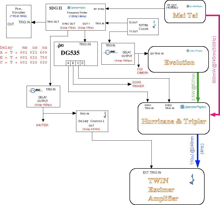 The beam stabilization system needs control signals from SDG II "out 1" and "sync out", so I have to change the timing again. I already modified the timing for the front end before (on July 7th), but I did not consider to trigger the Pockcel and TWIN AMP separately. Now I have to insert one more delay box such as BNC delay generator in order to trigger the TWIN AMP.
The beam stabilization system includes one CCD camera and one chopper, both of them also need the TTL pulses to trigger. The pulses from BNC #1 to trigger CCD, #2 to trigger the beam chopper.
Wednesday, November 15, 2006
JLab FEL Breaks Power Record
The most powerful tunable laser in the world has shattered another power record. Officials report that the free-electron laser (FEL) at the Thomas Jefferson National Accelerator Facility produced a 14.2 kilowatt beam of laser light at an infrared wavelength of 1.61 um on Oct. 30.
Tuesday, November 14, 2006
Heater and reservior voltage for TWINAMP
The TWINAMP could not be triggered by internal pulse correctly but only by external signal normally yesterday. By my early experience, the problem was caused by the thyratron heater and reservoir voltages. We measured the heater voltage(V_H) from the power supply output, which is about 10.2 VAC. When I decreased this voltage down to 9.4V (the minimum adjustment), the TWINAMP ran well. We also measured the voltages from thyratron side.
On May 1st, I set the Heater and Reservoir voltages: V_H=11.35V, V_R=8.35V. On Oct. 18, 2005, we set the voltages: V_H=7.05V, V_R=7.49V.
| Power Supply Output | Before filter | Before Thyratron | |
| V_Heater(VAC) | 9.30 | 7.80 | 7.50 |
| V_Resevior(VAC) | 7.78 | 7.48 | 7.48 |
On May 1st, I set the Heater and Reservoir voltages: V_H=11.35V, V_R=8.35V. On Oct. 18, 2005, we set the voltages: V_H=7.05V, V_R=7.49V.
Ultrafast, Intense Laser Captures Nanoscale Images
HAMBURG, Germany, Nov. 14, 2006 -- Using a single, extremely short and intense x-ray laser pulse, an international team of scientists have, for the first time, taken a high-resolution diffraction image of an object such as a protein before the intensity of the radiation destroyed the sample. The experiment was the first successful application of "flash diffractive imaging" and begins a new era in structural research.

The new method will be applicable to atomic-resolution imaging of complex biomolecules when even more powerful x-ray lasers, currently under construction, are available. The technique will allow scientists to gain insight into the fields of materials science, plasma physics, biology and medicine.
The scientists, part of an international collaboration led by Lawrence Livermore National Laboratory's (LLNL) Henry Chapman and Janos Hajdu of Uppsala University in Sweden, achieved the feat using the world's first soft x-ray free-electron laser, located at the FLASH facility at Deutsches Elektronen-Synchrotron (DESY) in Hamburg. Their work will appear on the cover of the December issue of the journal Nature Physics (12 November 2006 | doi:10.1038/nphys461).
The experiment suggests that in the near future, images from nanoparticles and even large individual macromolecules -- viruses or cells -- may be obtained using a single, ultrashort high-intensity laser pulse before the sample explodes and turns into a plasma. This means that scientists could better understand the structure of macromolecular proteins without crystallizing them, which is required in conventional x-ray structure analysis, and have the ability to rapidly study all classes of proteins.
(From Photonics.com)
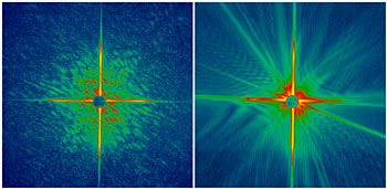
The new method will be applicable to atomic-resolution imaging of complex biomolecules when even more powerful x-ray lasers, currently under construction, are available. The technique will allow scientists to gain insight into the fields of materials science, plasma physics, biology and medicine.
The scientists, part of an international collaboration led by Lawrence Livermore National Laboratory's (LLNL) Henry Chapman and Janos Hajdu of Uppsala University in Sweden, achieved the feat using the world's first soft x-ray free-electron laser, located at the FLASH facility at Deutsches Elektronen-Synchrotron (DESY) in Hamburg. Their work will appear on the cover of the December issue of the journal Nature Physics (12 November 2006 | doi:10.1038/nphys461).
The experiment suggests that in the near future, images from nanoparticles and even large individual macromolecules -- viruses or cells -- may be obtained using a single, ultrashort high-intensity laser pulse before the sample explodes and turns into a plasma. This means that scientists could better understand the structure of macromolecular proteins without crystallizing them, which is required in conventional x-ray structure analysis, and have the ability to rapidly study all classes of proteins.
(From Photonics.com)
Friday, November 10, 2006
Low water pressure alert system
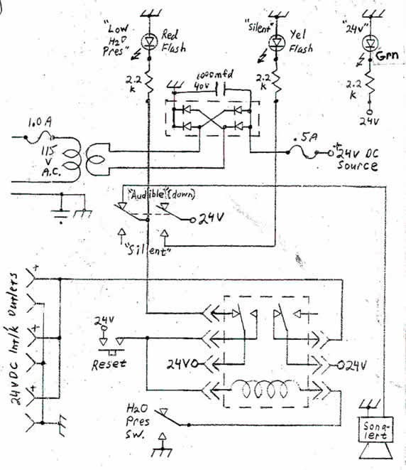 The water pressure alert system has been used in our lab for many years. When the city water pressure is low, the system will buzz loudly, then the 24V control signal will be shut down. This alert system looks simple but very useful. It is used to protect the diffusion pump water cooling for x-ray and YAG laser water cooling system.
From last week, the alarm kept buzzing. I had to set the alarm to silent. I opened the circuit box to check today and found the problem came from the reset button. When I pushed the button, the reset could not be short. So even the water pressure sensor operated well, the 24V power could not be applied to the relay coil. The alarm was recovered after the reset button was replaced.
Subscribe to:
Posts (Atom)