I can run a program under Labview to send or query RS-232 commands only by pushing buttons. The front control panel and LabView block diagram are shown here.
 I can run a program under Labview to send or query RS-232 commands only by pushing buttons. The front control panel and LabView block diagram are shown here.
 I found the resistors connected to the 40184 spark gap was broken, which caused the misfire for the Prometheus. This 40184 spark gap(SG1) was installed inside the 50kV trigger generator box. SG1 is a three electrode, 2:1 gap-space, irradiated-gas-plasma switch. The switch operates in the swinging cascade mode in which the intermediate electrode is biased at one-third of the working voltage.
Indication | GPIB address | Termination | Mode | |||||
| Switches | 1 | 2 | 3 | 4 | 5 | 6 | 7 | 8 |
| ON/OFF | OFF | OFF | OFF | ON | OFF | OFF | ON | ON |
| Note | This address matched the scope GPIB address | LF termination | C | |||||
Indication | bits per second | Parity | Check | Stop | Data | Flow | ||
Switches | 1 | 2 | 3 | 4 | 5 | 6 | 7 | 8 |
ON/OFF | ON | OFF | ON | OFF | OFF | OFF | ON | OFF |
Note | 9600 baud | Odd | Disable | 1 bit | 8 | Disable | ||
 Yesterday we found the small mirror surface of the beam expander was damaged, we figured out that it was caused by the laser beam filament or self-focusing. We improved the spatial filter vacuum, covered the optical tables, cleaned the windows, and filled the new gases into TWINAMP. All these behaviors might increase the laser output energy, which finally provoked the strong nonlinear effect such as filament or self-focusing.
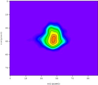
 We measured the beam profile and wavefront of tripler (see the right figure). M2(X)= 1.58, M2(Y)=1.56; Beam width(X)= 3.3 mm, Beam width(Y)= 2.9 mm.
 In 1670 Isaac Newton demonstrated the composite nature of sunlight when he sent a carefully collimated sunbeam through a prism, which spread out the light into a rainbow of colors; by sending a beam of single color through a second prism (with no further spreading) Newton showed that the color was not being imposed by the prism but was intrinsic to the light itself. Now physicists using the Advanced Photon Source at Argonne National Lab, in Illinois, have spread out a beam of X-rays (which are, after all, just a more energetic version of visible light) into a rainbow of colors.
 In the Thales laser-control architecture, supervision software controls, through an RS232 connection, a laser-control system that drives all individual control units and drivers; a femtocontrol unit that drives the diagnostics; one or several synchronization units, CCD cameras and diagnostics; and all connections between computers, power supplies, electronic racks, and breadboards (see Figure).
 a, In Faure and colleagues' experimental scheme, the primary laser wakefield pulse ionizes helium gas to a plasma. If the parameters of pulse and plasma are chosen appropriately, the electrons of the plasma oscillate about a fixed spot. b, If a second 'tow-in' pulse travelling in the opposite direction crosses the first, a standing wave forms. Electrons are pushed left and right in the standing wave from the antinodes to the nodes. c, Some electrons — those pushed to the right — gain enough speed to get caught up in the following wave crest and are accelerated forwards. The energy gain of the electrons is determined by how far they have to surf through the plasma, and so by where exactly along the plasma the two laser pulses cross.
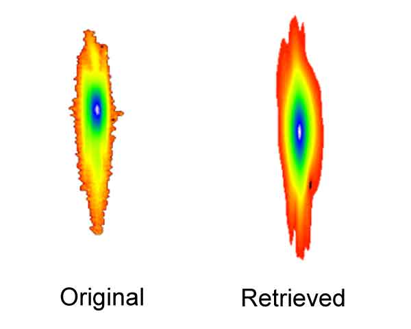
 A new configuration for a two-dimensional (2D) imaging x-ray spectrograph based on a conically bent crystal is introduced: extreme luminosity imaging conical spectrograph (ELICS). The ELICS configuration has important advantages over spectrographs that are based on cylindrically and spherically bent crystals. The main advantages are that a wide variety of large-aperture crystals can be used, and any desired magnification in the spatial direction (the direction orthogonal to spectral dispersion) can be achieved by the use of different experimental arrangements. The ELICS can be set up so that the detector plane is almost perpendicular to the incident rays, a good configuration for time-resolved spectroscopy. ELICSs with mica crystals of 45×90 mm2 aperture have been successfully used for imaging on the XP and COBRA pulsed power generators, yielding spectra with spatial resolution in 2D of Z pinches and X pinches. ©2006 American Institute of Physics
 This year's 10th annual German Innovation Award has been awarded to Stefan W. Hell, the director of the Max Planck Institute for Biophysical Chemistry, for his project "Light Microscopy with Unprecedented Resolution".
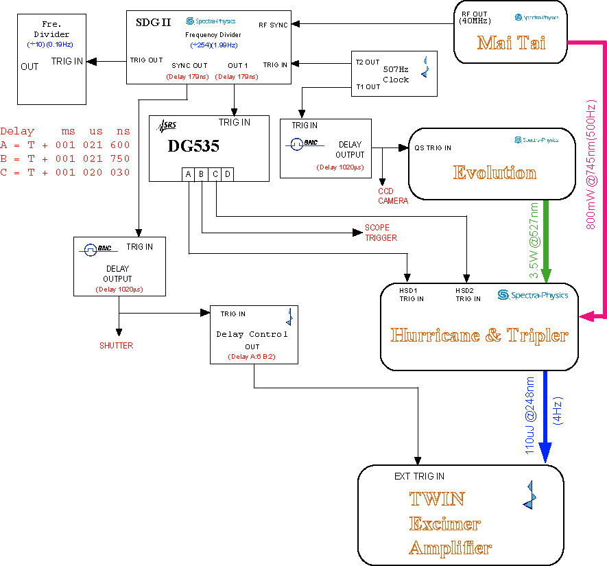 The beam stabilization system needs control signals from SDG II "out 1" and "sync out", so I have to change the timing again. I already modified the timing for the front end before (on July 7th), but I did not consider to trigger the Pockcel and TWIN AMP separately. Now I have to insert one more delay box such as BNC delay generator in order to trigger the TWIN AMP.
| Power Supply Output | Before filter | Before Thyratron | |
| V_Heater(VAC) | 9.30 | 7.80 | 7.50 |
| V_Resevior(VAC) | 7.78 | 7.48 | 7.48 |
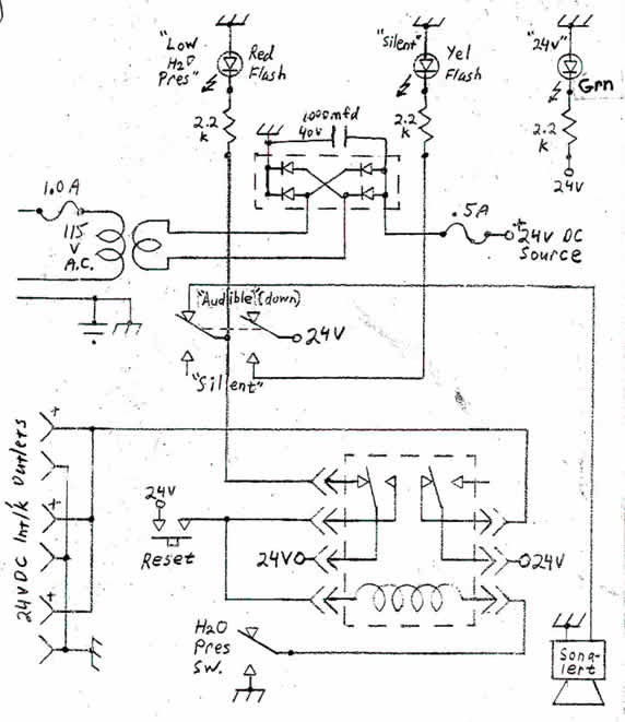 The water pressure alert system has been used in our lab for many years. When the city water pressure is low, the system will buzz loudly, then the 24V control signal will be shut down. This alert system looks simple but very useful. It is used to protect the diffusion pump water cooling for x-ray and YAG laser water cooling system.
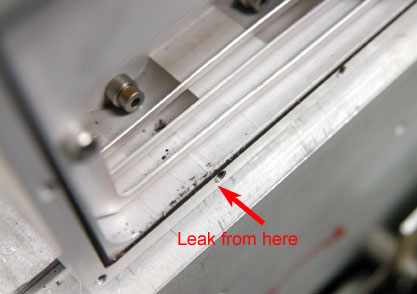 We cleaned all TWINAMP windows, filled 400mbar F2 + 1400mbar He for leakage detection last night. We found the pressure was dropped by 50mbar for the long tube, and we could smell pungently. Because the o-rings for window and PVDF plate were changed last month, maybe the gas leak came from the aluminum box connected to the window frame. We found some black grain in the aluminum box. The o-ings were changed immediately.
 The Prometheus gases has been changed.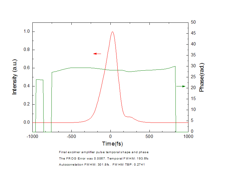

 Electrons, protons and even ions can be accelerated using the extreme electric fields generated when a high-power laser is focused into a plasma. But the structure of the so-called laser wakefields that are driven through the plasma at almost the speed of light — analogous to the wake produced behind by a boat as it travels on water — has until now only been discernable through simulations of the process. Nicholas Matlis and colleagues have produced the first direct images of a laser wakefield, by using a holographic technique that reconstructs an image of the wake structures from the way in which they perturb the interference of two coherent light beams passing through the plasma. The technique provides a new tool for studying laser–plasma interactions and potentially improving the performance of laser-driven particle accelerators.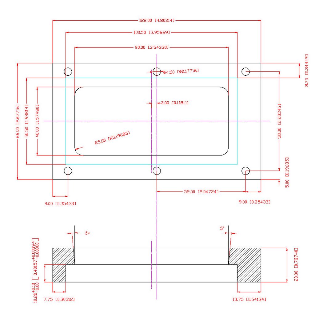
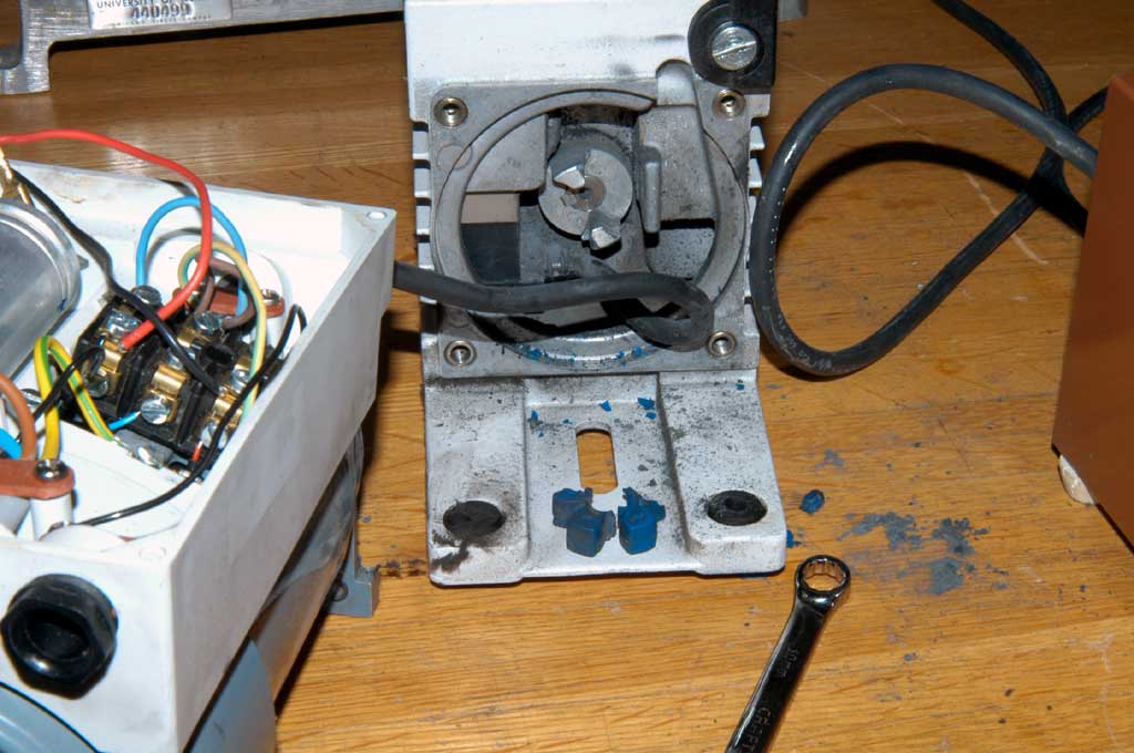 We used the rotary vane pump to vacuum the first spatial filter for TWIN system, this pump could not work two weeks ago. At first, we guessed the start capacitor was broken, however the pump did not work any more even we changed a new capacitor. Mike helped to separate the motor and the rotary vane, he found the motor worked well. The problem was the spider coupling was broken.
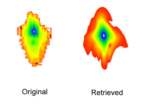
 We used the new FLI back illuminated CCD to take the FROG picture. I found this new CCD camera very sensitive to the UV light compared with our old CCD. For the old one, we had to expose about 5 seconds to take Hg I 248 nm line, for this new one, it's only about 30 ms.
|
Purging | Image Quality Software A/D serial Number: #3329 Final Check, no frost visible@ -15 C
|
 Progress continues apace in the development of laser wakefield accelerators, which produce high-energy beams of electrons, atoms and molecules using the extreme fields generated in a plasma by high-power lasers. But for the potential of these devices to be realized — in practical applications that range from studying the behaviour of matter under extreme conditions to proton therapy for the treatment of deep-seated tumours — the energy of the particle beams they produce must reach the giga-electronvolt range. Initial estimates had suggested that reaching such energies would require lasers capable of producing pulse powers of the order of petawatts. But Wim Leemans and colleagues have proved the predictions wrong by producing 1-GeV electron beams using only 40 terrawatts of laser power — the trick being to focus the laser into a 3.3-cm-long gas-filled capillary discharge tube.
Lasers consist of an active medium of excitable atoms, a pumping mechanism for exciting those atoms, and a cavity for building up a pulse of coherent radiation. At the Institute for Heavy Ion Research (Gesellschaft für Schwerionenforschung, or GSI) in Darmstadt, Germany, scientists have succeeded for the first time in using a beam of uranium ions as the pump for producing ultraviolet laser light.
It works like this: the uranium beam ionizes argon atoms, which ionize krypton atoms, which in turn form excited molecules with fluorine. The krypton fluoride molecules are the excited entities which emit coherent light at a wavelength of 248 nanometers. A laser that uses this rare gas-halide mixture is called an excimer (excited dimer) laser.
This is not the shortest laser wavelength ever achieved, and the uranium pumping scheme is not all that energy efficient. So why then use this approach to producing laser light, especially when electrically pumped commercial krypton fluoride lasers are available? Because this was a test run for producing laser light in excimers that can't be electrically pumped.
According to Andreas Ulrich of the Technical University of Munich (andreas.ulrich@ph.tum.de), the goal is to excite excimers of pure rare gases for producing radiation in the VUV (vacuum ultraviolet) and soft X-ray region of the spectrum. Only now have uranium beams at GSI been powerful enough to provide the pumping power for lasers in this wavelength region. Being so heavy, uranium atoms deposit their energy into a gas much more efficiently that lighter particles such as electrons.
Ulrich et al., Physical Review Letters, 13 October 2006
Contact Andreas Ulrich
Technical University of Munich
andreas.ulrich@ph.tum.de
Copied from
 The compound refractive x-ray lenses (CRLs) are used to focus and collimate hard x rays, and image objects using hard x rays. The lenses have been experimentally shown to operate in energy ranges from 4 to 80 keV, at focal lengths as small as 5 cm, with numerical apertures of 10-3 or better. These operational ranges can be further extended.
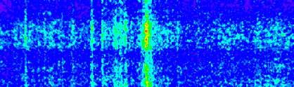 We tried to record the first order spectra many times, however we only got a single spectral line. Today we reduced the gas pressure and moved the focal spot a little behind the nozzle center, we also increased the MCP voltage(~1 kV) and phosphor voltage (~4 kV). We observed the soft x-ray spectrum successfully, we will calibrate these spectra soon.
 We installed a new parabolic reflect mirror to focus the laser beam and adjusted the alignment of the spectrometer. In order get the signal, we changed the nozzle repetition rate to 0.5 Hz, the gas pressure decrease around 100 psi. Compared the last zeroth order spectrum, this looks very bright and sharp. The line became very weak when the nozzle was not triggered, it means that there was only 248 nm laser hit MCP.
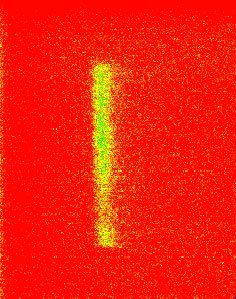 We are using a 1-meter 86 degree grazing incidence model 247 McPherson spectrometer to measure the soft x-ray emission from laser plasma interaction. The detector is a single stage 2 inch diameter MCP with a potential of between of 200V to 1kV across it. The electron burst from the MCP is accelerated by another potential of 3 kV to 5 kV into a phosphor screen. The green photons from the phosphor is collected by a camera lens and sent to CCD camera. By adjusting the spectrograph, we obtained the 0-order spectrum.
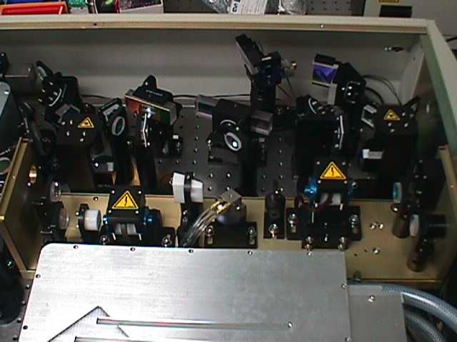
 The compressor consists of one grating, one horizontal retromirror set, and one vertical retro-mirror.
 (1). Blcok the Mai-Tai seed beam.
 The seed beam was sent to the target chamber after expanding beam size from 3 cm diameter to around 10 cm diameter, then it was focused to the smaller spot by a Parabolic mirror. We are using the 248 nm coated paroblic mirror with 20 cm focal length, so the focal spot under the diffraction limitation is about 1.2 um.
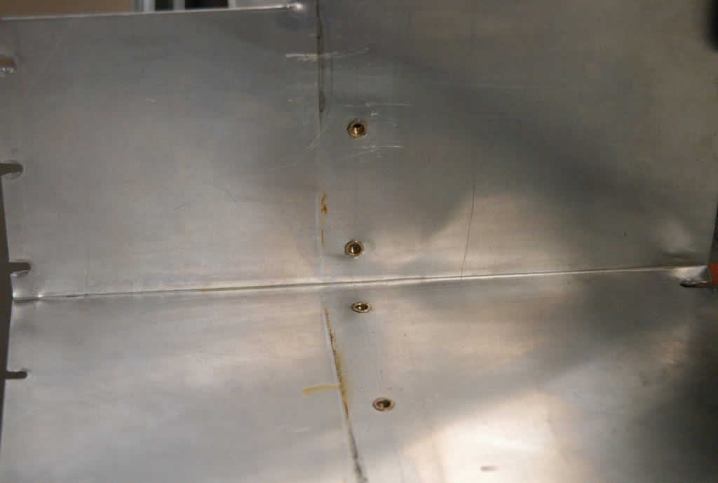 Last month, we found the arcing problem when running the LLG-TWIN excimer amplfier, I put a teflon plate for preventing the sparks. Today the arcing happened again, I am afraid the isolation plate could not really avoid the arcing. With Randy and John's helps, we removed the alumina plate and found the spark traces on plate of thyratron side.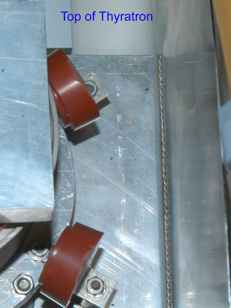
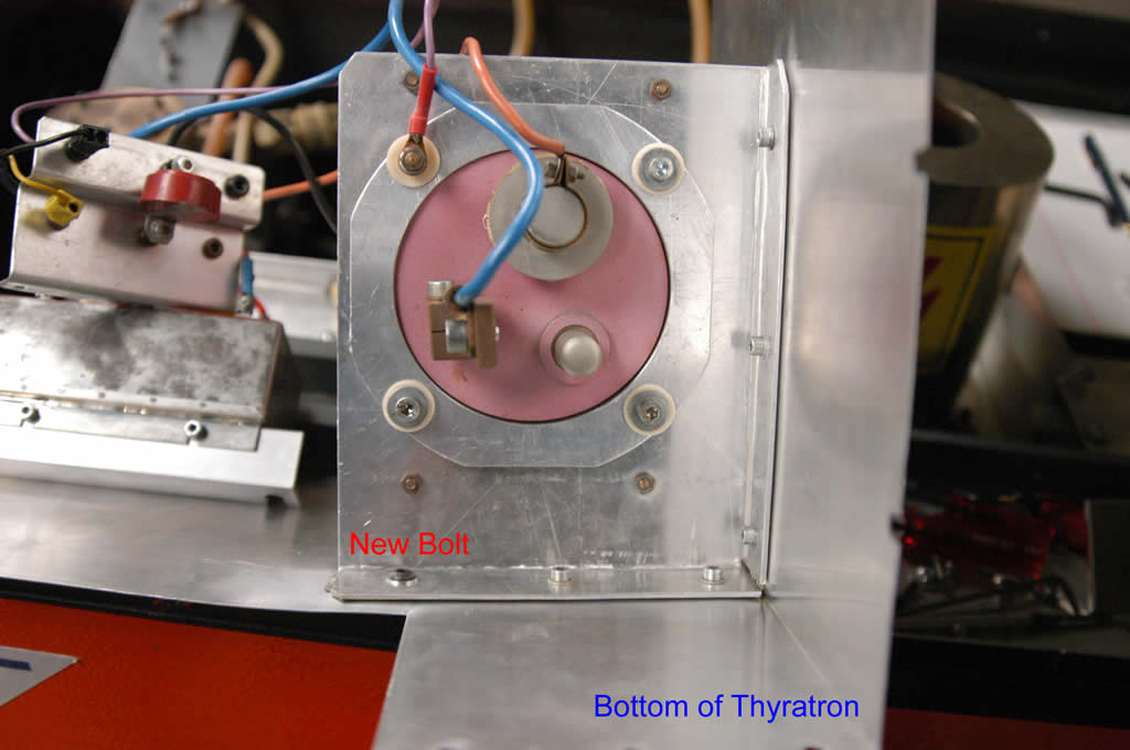 plates tightenly. A wire braid was inserted between the plates in order to avoid the arcing.
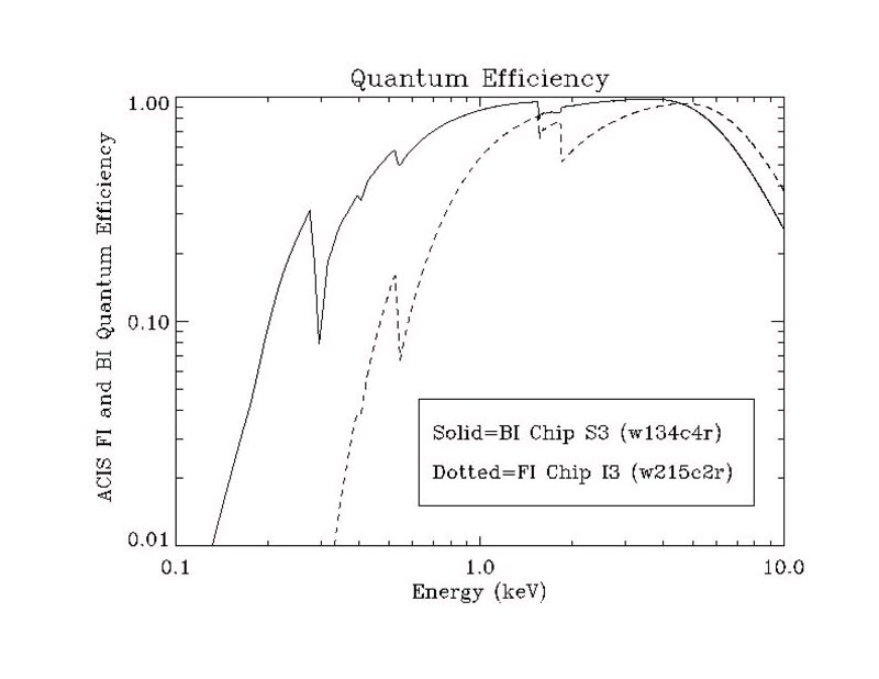 A conventional CCD consists of a sandwich of semiconductor layers overlaid with a network of "gates", electrodes which serve to transfer charge from one pixel to another as the device is read out. At low energies (E<1>5 keV). due to photon loss through the front of the back-illuminated device.
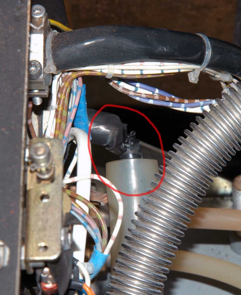 In the afternoon, the TWIN excimer amplifier suddenly stopped firing after running for half hour. I found the power supply light became red, the light was off after pressing the reset button. Then I pushed the H.V. button and Laser button, I heard a buzz sound inside the excimer chamber. I energized gradually to the amplifier, the voltage reached 12 kV, the buzz appeared again then the system shut down immediately.
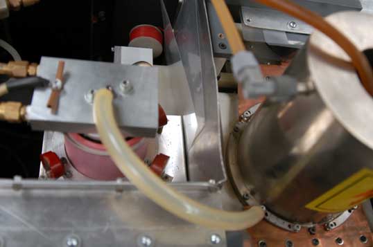 When I ran the TWIN excimer amplifier, I could hear the crack sound inside the chamber. This phenomenon was happened before, which was caused by the spark from the Thyratron plate and ground plate. I put two picece of plastic sheet to isolate them. Probably the sheet became dirty or they were too thin. The Thyratron plate should be tightened with the real ground plate in order to avoid the spark, however it will take several days to remove the plate to drill the holes for tightening. The simple way is to replace the isolating plate with a new teflon plate. After replacing, the system ran well.
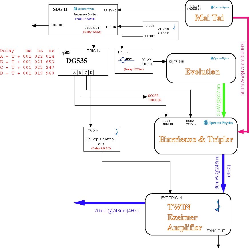 In order to synchronize the seed pulse and Prometheus ASE, I tried many ways without using more delay control equipments. But all the attempts were failed, I have to consider change the front end timing. By studying the old system timing, I found a 10ms delay was added to the CAP pump Q-switch laser, I could copy this setup for our new system. So I inserted a 1ms delay by using BNC delay controller, then replaced the original delay controller from LLG with SRS DG-535. The channel A of DG-535 was used to switch Pockell in and channel C for Pockell switch out. The output of channel D was used to control the excimer control box.
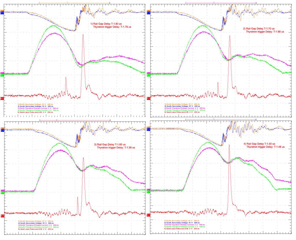 I tried to match the seed laser beam and the Prometheus ASE. The Prometheus ran in the good condition when Thyratron trigger and X-ray Anode trigger was set by 1.78 us and 1.22us earlier than Railgap trigger respectively. So the time delay between seed pulse and Prometheus could not be set less than 1.78us. I tried to adjust the time delay from 1.8us to 1.5 us (as shown in the pictures). I found when time delay was 1.5us, two pulses were overlapped, but the thyratron current wave forms indicated the Thyratron had no time to totally turn off.
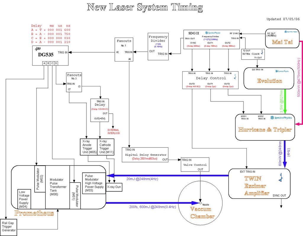 We simplified the timing setup when we installed the new High Voltage power supply. The prevent circuit has been removed, the Thyratrons were triggered directly by the signal pulses from SRS DG-535. The repetition rate was decreased by 0.2 Hz for Prometheus, the 4 channels were set as A=T+1 ms, B=A-1.75 us, C=B+30 ns, D=A-1.21 us.
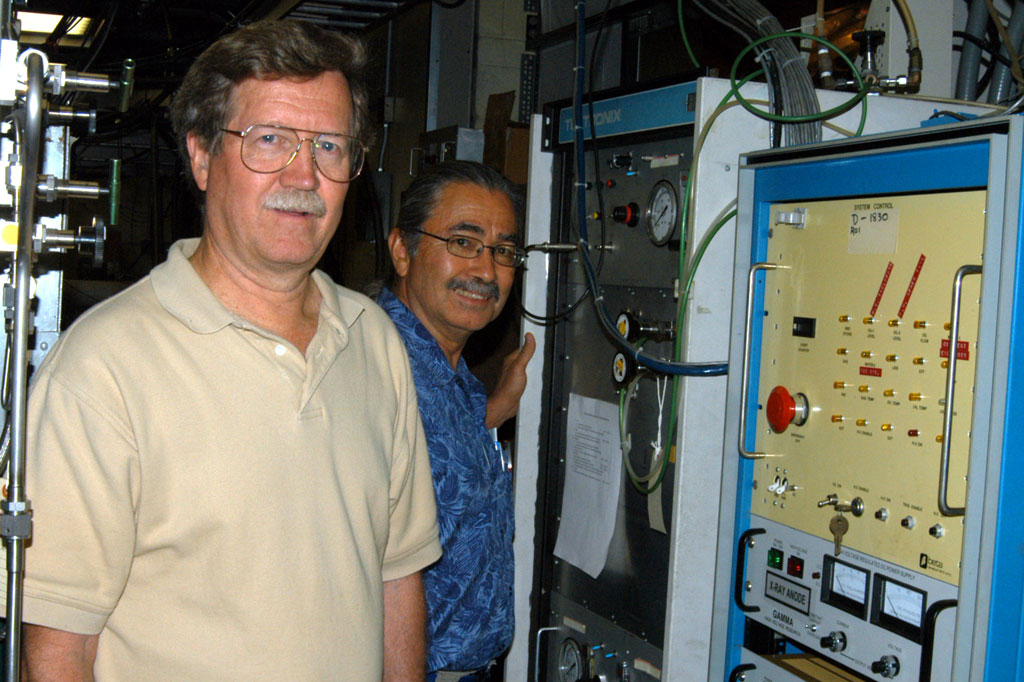
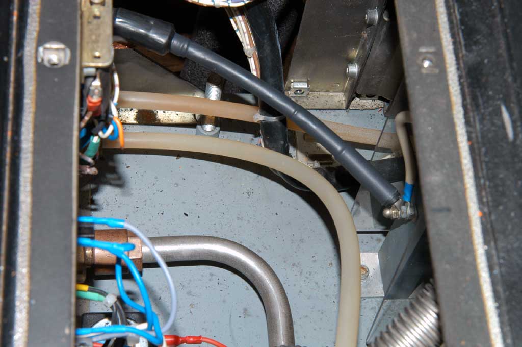
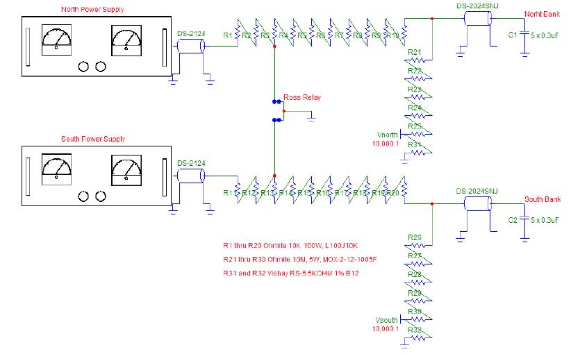 The SCR Controller, SCR Power Block, HV Transformer with current limiting resistor, HV rectifier diodes, charging and dump resistors, LED status lights, Trigger Inhibit boxes, and all control and coaxial cables that went to the main control rack were removed. These functions were replaced by a new dual charging board and two Gamma Power supplies as shown the right picture.
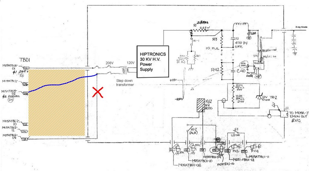
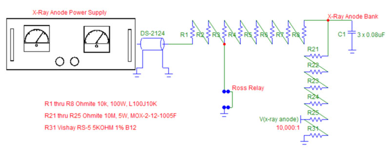 The X-ray anode charging board utilizes eight 10K, 100W Ohmite wirewound resistors that serve to isolate the Gamma power supply and additionally provide an energy dump via the Ross relay. Resistors R3 through R8 are used to dump about 110 joules of stored energy in the three 0.08uF capacitors when charged to 30 kV. Resistors R1 and R2 can be used to set the constant current charging current limit of the Gamma power supply when the Ross relay is left de-energized. Resistors R21 through R25 and monitor resistor R31 provide a 10,000:1 voltage divider to be terminated into 1 Megohms or greater for power supply calibration purposes. This divider is not resistor-capacitor compensated and is not intended to observe fast discharge pulses. The 50-Megohm-divider string also provides a slight bleed for the power supply to help hold the charge voltage accurately.
 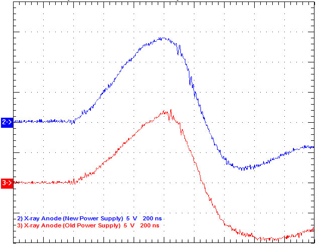 The X-ray Anode unit was operated at a constant charging current of 5 ma and a charge voltage of 27 kV giving a dose rate of about 0.4 mR/hr from the X-ray Anode electron source. The constant current charging time can be estimated to be T = CV/I = (0.24uF)(27kV)/(5ma) = 1.30 secs. In actuality, the charging time is a little greater due to the slight voltage drop across the charging resistor string as the power supply switches from constant current to constant voltage operation as the final charge voltage is reached. This power supply portion of Prometheus is compatible with 0.4 Hz operations. The scope trace as shown right picture compares the previous X-ray anode results with those of the new power supply system. The X-ray pulse is slightly higher and faster due to the lower inductance associated with a better layout and grounding of the capacitors in the X-ray Anode HV Tank.
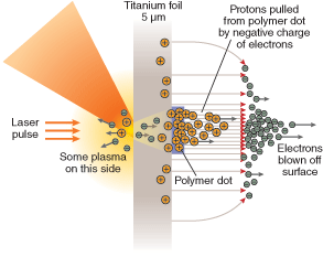
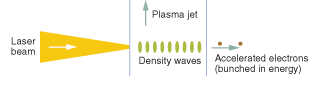 Wake-field acceleration is often compared with surfing. When an intense laser pulse hits a plasma, it creates a density wave of free electrons. The electrons, in turn pull positive ions-protons or heavier nuclei-along with them, creating a density wave as they pass through the plasma (see Fig. 1). The density wave carries the free electrons with it, and the electrons can reach 100-MeV energies within a millimeter, roughly 1/5000th the distance needed in a conventional accelerator.
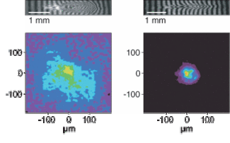 A major advance came in 2004, when three groups reported much narrower ranges of electron energy in papers that appeared in the same issue of Nature.3, 4, 5 The key to their success was finding ways to inject a clump of electrons into a small part of the plasma so the electrons can be accelerated collectively to nearly the same energy. The researchers fired pulses with peak powers of 10 to 30 TW and lengths of 30 to 55 fs into gas jets 2 mm long. By creating plasma channels or adjusting the laser beam to guide the density waves through the jets, they managed to constrain energy spread to no more than 24% for up to a few billion electrons (see Fig. 2).