Friday, December 23, 2005
Wednesday, December 21, 2005
Captive nuts
 I ordered captive nuts from McMaster-Carr, the part number is 95185A191: Zinc-Plated Steel Clinch Captive Nut 10-32 Screw Size, .091" Minimum Panel Thickness, the style: Hex Head Clinch Style. However they delieved wrong captive nuts.
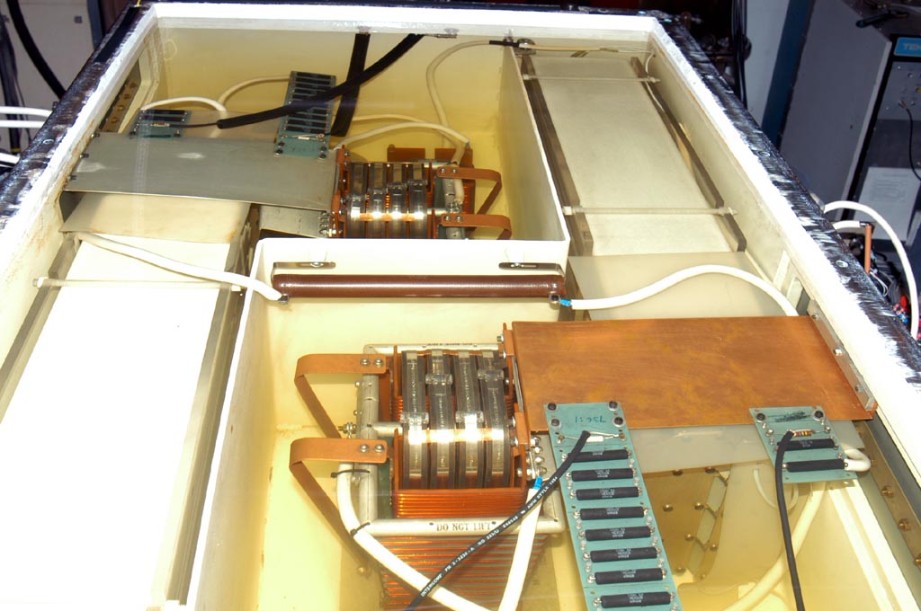
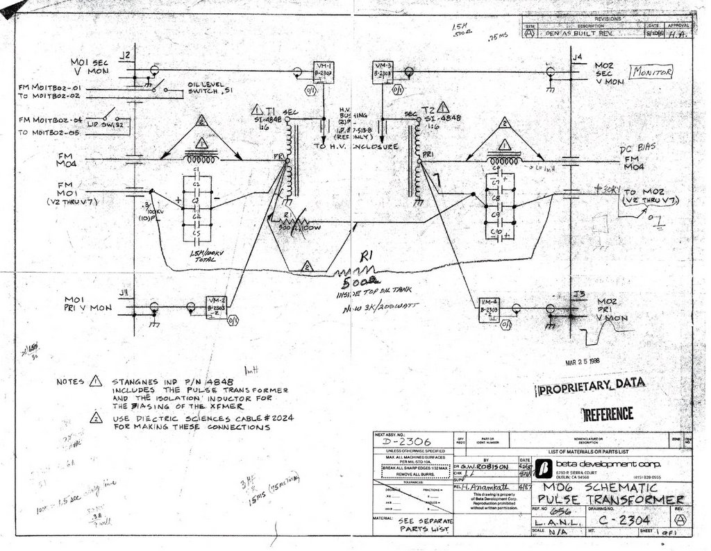 The above is the MO6 pulse tranformer schematic drawing, Keith and Bill replaced the 500 Ohm 100W resistor with 3k Ohm 200W resistor before. Keith said it's not big deal to use a 1.5k Ohm resistor.
Tuesday, December 20, 2005
Moving the caps from South Bank
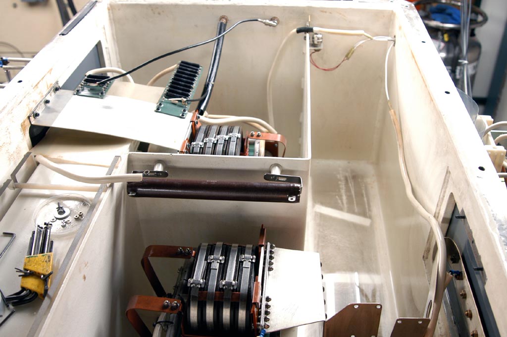 We moved the capacitors from the South Bank, I found this side was clearer than North Bank, since we cleaned south last year. Mike checked the power supply for Anode Thyratron filament, he could not find any problem. The caps and choke are all right.
The
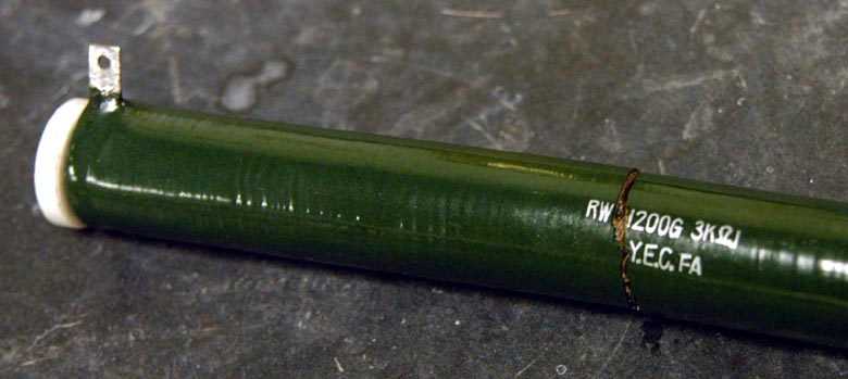 other trouble is the resistor connecting South Bank caps and North Bank caps, it's broken when I tried to disconnect the cable. This resistor is 3k Ohm, 200 Watts, I did not find the same resistor from electrical shop. They only have 1.5k Ohm, 225 W resistors. I am not sure if I can replace 3k Ohm with 1.5k Ohm. From the circuit drawing, I found the original resistor was 500 Ohm.
Monday, December 19, 2005
Cleaning the top oil tank for North Bank
 I asked Mike to check the X-ray anode thyratron filament power supply, because Keith guessed the capacitors or chokes for this power supply may not be well.
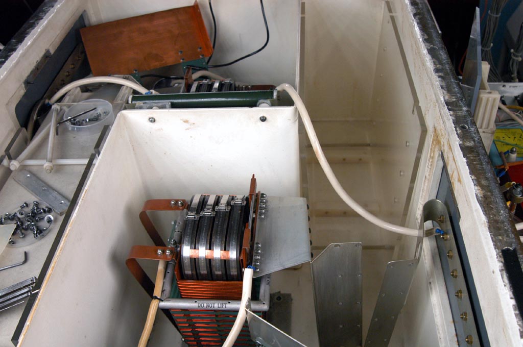 I pumped oil out from the top oil tank and found caps surface were very dirty. I took 5 pieces of capacitor for cleaning, and put them for drying over night. I will put them back tomorrow morning, and clean the south bank caps too.
Friday, December 16, 2005
Cleaning the 0.3 uF caps
This morning Mike helped me to measure three capacitors. We used Hipotronics 30kV 5mA power supply, connected 10k Ohm resistor and measured capacitor. When the voltage was slowly increased to 30kV, the current was around less than 0.1mA. It means the caps were good. We only heard a little click from one cap, it may be caused by the dirty surface. So I cleaned all the capacitors, then installed after drying.
I tested the system again in the afternoon, however I could hear the click sound from the oil tank, the voltage could not reach 150 kV anymore. I could not receive any signal from X-ray meter. I heard crack noise from the top oil tank at the same time. When I measured the voltage of the south bank and north bank, I found the north bank voltage was fine, but the south bank voltage was missed one to two per 10 shots. I am wondering if the rail gap trigger effects the x-ray gun? I plan to clean the top oil tank next Monday.
I tested the system again in the afternoon, however I could hear the click sound from the oil tank, the voltage could not reach 150 kV anymore. I could not receive any signal from X-ray meter. I heard crack noise from the top oil tank at the same time. When I measured the voltage of the south bank and north bank, I found the north bank voltage was fine, but the south bank voltage was missed one to two per 10 shots. I am wondering if the rail gap trigger effects the x-ray gun? I plan to clean the top oil tank next Monday.
Wednesday, December 14, 2005
High Voltage Cable Connector
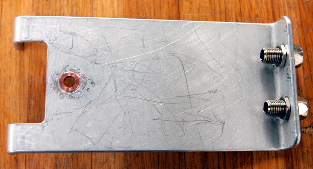 Kevin helped me refurnish the anode connect plate, which looks pretty good. He put a copper hole to replace the arcing hole.
I also cut the 150kV cable end and thread it. But it's very hard to put the cable back to the cap tank. Finally I put it into the tank, but it's silly not to fix it very well, there was oil leak from the connector.
Tuesday, December 13, 2005
Hipotronics Power Supply Output Cable
 In the morning, I checked the HIPOTRONICS 30kV DC Power Supply. When this equipment was open, the voltage monitor showed 30 kV as I set the output to full scale. When I took out the output cable, I found the cable end was burned because of the arcing. I contacted Hipotronics company, they will charge us $190 for a 3 feet cable and it will take a week for delivery. Fortunately I found a similar cable in the cabinet, I cut it to fit the power supply. But it's weird that click sound still has been heard inside the oil tank, I did not find the key to make the x-ray anode trigger failed.
The only part I have not checked is the 150 kV cable connector with the capacitors, I already drained the cap oil tank. I will check the connector tomorrow.
Monday, December 12, 2005
X-ray Anode Trigger Unstable
 We are lucky to find a 33 Ohm resistor from electrical shop. Then I pumped the oil out and installed the resistor, at the same time I checked the connectors of transformer, capacitors, choke, thyratron and charging resistors, and found some screws not tight. I tightened the loose screws then. But the x-ray anode could not be triggered normally. I still heard the clicks inside the oil tank and the high voltage could not reach 150 kV yet, which I described in my last email. An interesting phenomena is when I decreased the DC power supply voltage from 30 kV to 20-15 kV, I could not heard the clicks inside the oil tank. What caused this phenomena happened?
I also checked the anode control box, the input signal looks very good. I replaced the high voltage trigger for thyratron, the problem was still there. Till now, I checked every components except the 30 kV DC power supply and the Anode cable connector.
Friday, December 09, 2005
33 Ohm Resistor
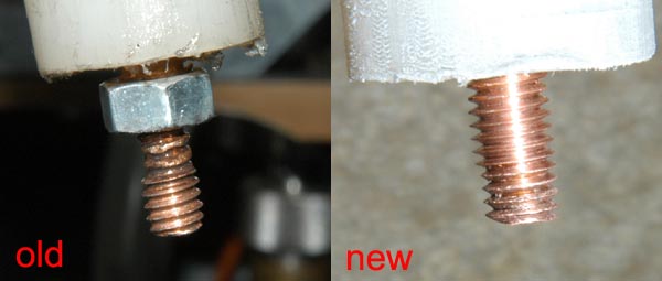
 I put the PerkinElmer new thyratron HY-3202 into the x-ray anode control box this morning, but the anode trigger was not well yet. The x-ray anode high voltage was about 100 kV, I guessed there were some place breakdown in advanced. I checked the connectors in the oil tank, all of they looked very well. I pumped the slicon oil into the oil tank and tested the system again. I found there were arcings from the resistor which connected to the step up transformer. I took that resistor to check and found its surface not very good, there are many small holes. Please look at the picture, I marked the holes using the red circle. I think maybe the discharg was from the resistor surface and the ground.
Caution of HY3202 Installation instructions:
1. Keep tube envelope clean. Handle only by base, flange and anode stud. GLOVE SHOULD BE WORN.
2. Don't exert any force on pins, feedtrus or leads. Avoid any bending of pins. Don't carry tube by lead.
3. NEVER reduce reservoir voltage below 5.8 VAC. Tube can be destroyed.
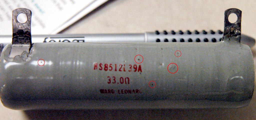 The manufactor was Ward Leonard, model number is KS8512L39A, the resistence measured around 33 Ohm. I have not found this company from Internet. From Ohmite web site, I did not find the similar resistor. I phoned Bill, he said this resistor was used for prevent the high voltage kick back. He remembered that he had some resistors in the electric storge, I will ask Mike to find one next Monday. What if we could not find the resistor? Should I replace it with 40 Ohm or 50 Ohm resistor(I can find them from Ohmite company)? Could you tell me what power is this resistor?
Bill also reminded me that the dirty oil could cause the arcing, or the high voltage cable problems.
Thursday, December 08, 2005
X-ray Anode Trigger Failed
 We received the 10k Ohm resistor this morning, then I installed it. In the afternoon I tried to passivate the system, it ran well until 4:30 pm. Then I heard clicks from the x-ray anode oil tank, the x-ray flux meter did not show any signal. I checked the reservoir and heater voltages for anode torturing, they were all fine. At the same time, the x-ray anode voltage monitor showed the high voltage could not reach 150 kV, it only went to 100 kV, then the voltage was dropped down to 50 kV (I heard the click from oil tank). This caused the x-ray gun running randomly, the system synchronization was failure. After checking the circuit drawing, I think there are three possible reasons to cause x-ray anode failure: 1) either SCR1 or SCR2 broken; 2) relay K1 control failed; 3) thyratron and its control unit not well. I plan to change the thyratron firstly tomorrow, then check SCR and relay K1.
The another bad news is the new Lecory oscilloscope is not working, so I could not save the waveforms.
Wednesday, December 07, 2005
Optical Path Alignment
I placed order of the 10k Ohm 225W resistor this morning, it should be received tomorrow morning. So I cannot run the Prometheus today. I checked the other part of the charging resistors, it looks good except some connectors. I fixed the connectors later. Mike helped me to find some resistors, unfortunately they were 100k Ohms.
In the afternoon, I aligned the optical path of the front end. The main point is the telescope alignment, it took me several hours to send the laser beam straightly into the Prometheus machine. I also found the first 2 mirrors not damaged, but the last one or two mirrors not good. I could see the shadows from them, it means the structure was broken inside.
In the afternoon, I aligned the optical path of the front end. The main point is the telescope alignment, it took me several hours to send the laser beam straightly into the Prometheus machine. I also found the first 2 mirrors not damaged, but the last one or two mirrors not good. I could see the shadows from them, it means the structure was broken inside.
Tuesday, December 06, 2005
Prometheus running
 I changed the north bank thyratron CX1585 firstly. I replaced the damaged rectifier diodes ECG 5912 as soon as I received diodes from moyerelectronics. When everything was installed, I tried to run the system this afternoon, it's fantastic to hear the shooting sound again. I measured the CX1585 filament voltage, it's about 6.1 V DC. The x-ray gun cathode pulse could move forward to match the x-ray anode peak, the x-ray flux was measured about 2.5 mR/h.
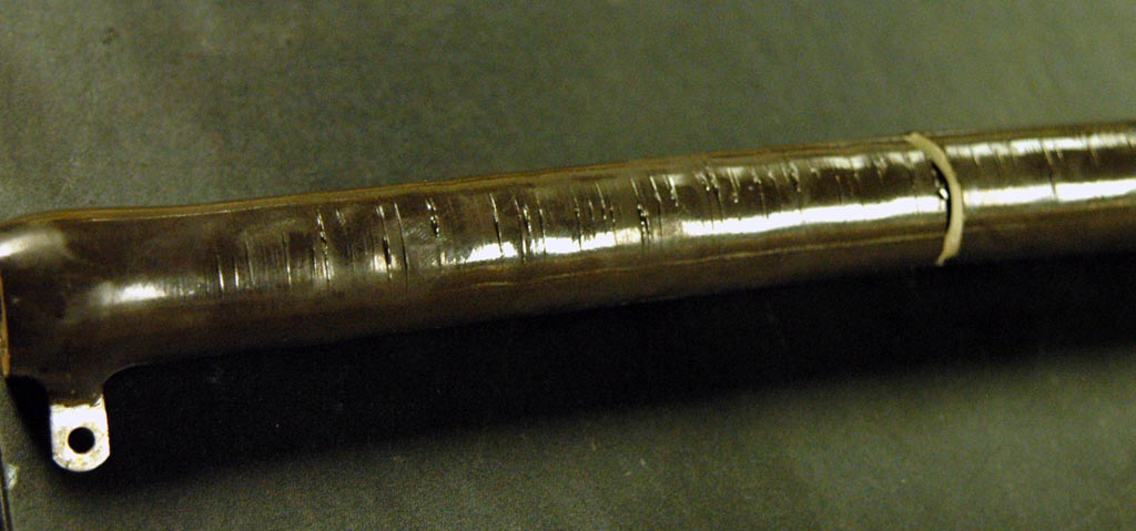 The passivation was proceeded later, I filled a little bit fluorine gas into 1.2 bar He-filled chamber. In the beginning, the emission light was red, after running a couple of minutes, the light became white. Then I filled a little bit more fluorine gas, this time the red light kept almost one hour until I found a 10 k Ohm resistor was burning. This resistor was connected to the big transformer, it was very hot when the system running. Maybe because the temperature was too high, the connector was burned and the resistor became very crisp. It was broken as I took it out. Anyway I must put a new resistor tomorrow.
Monday, December 05, 2005
Big Rectifier Diodes
I checked the other rectifier diodes for Rail Gap thyratrons, I did not find any one was broken. As for the reason the ECG 5912 diodes were breakdown, I think the north bank thyratron CX1585 may be the key, when we ran the system I could see the arcing from the north bank. Maybe this disturbed the circuit and sent back a noise to the diode?
Today I ran the Spectra-Physics fs laser, it looks very well.
Today I ran the Spectra-Physics fs laser, it looks very well.
Saturday, December 03, 2005
Fuses Checked
 ===============================
 Charlie and Song,
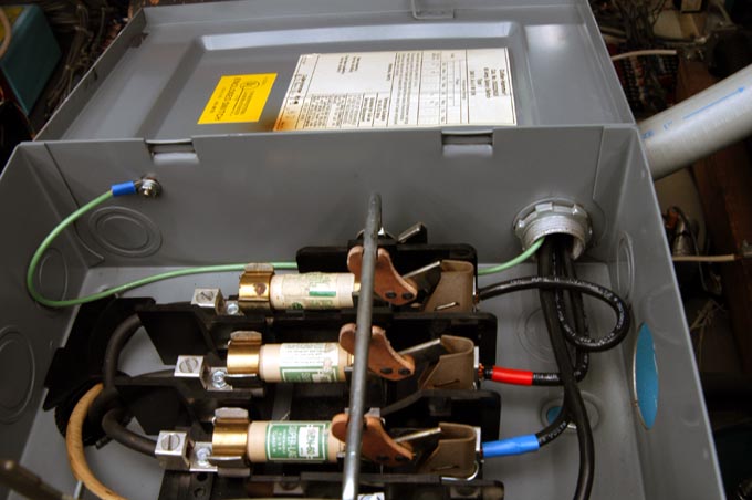
It is important to check the fuses in the box that we close and open to run the machine. These are in the top of Promethius and furnish a three phase power to all of Promethius. Their resistance should be measured across each fuse when the switch is open.
RegardsKeith
================================Along the Keith's email as above, I checked the fuses in the Prometheus power switch box, they are all fine. I also checked the 3 phase voltage, they are good, too. Please see the picture, make sure the switch box is corrected.
I pumped the gases out from the LLG-Twin Excimer front end, these gases has been kept inside the chamber for one month, I am afraid the F2 gas may corrade the O rings. I filled ~1 atm Helium gas inside the both tubes.
Friday, December 02, 2005
Silicon Power Rectifier Diode -- ECG5912
I checked the x-ray cathode trigger box this morning, 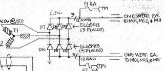 and measured the output voltage of transformer. I did not find anything wrong, but the cathode pulses was not good. There must be something wrong, the only part was not checked is thyratron filament voltage.
I measured that voltage, which was 2.7 V. It's lower than the normal value of 6.3 V. From the circuit drawing, this power was provided by M04 Low Power Supply. Please look at the attached picture, the 6.3 V DC is sent to M01, M02 and M11. M01 and M02 for rail gap, M11 for x-ray cathode. It may be two possible cases to decrease the low voltage, one is the thyratron of M01, M02 and M11 not working well, the other is the rectifier diode breakdown. I disconnected the diodes D7-D12 to check, and found D7 and D9 were totally breakdown, so the output voltage dropped to 2.7 V DC. This caused the thyratron CX1585 unstable, which finally effects the x-ray cathode pulses. I think the damaged diode is the main part to make the whole system failure. I did not find any replaced diodes in the lab, the electrical shop was closed when I found the problem. I will ask Mike to find the diodes ECG 5912 or order them next Monday. I hope the system would be run well after I replace the diodes.
 and measured the output voltage of transformer. I did not find anything wrong, but the cathode pulses was not good. There must be something wrong, the only part was not checked is thyratron filament voltage.
I measured that voltage, which was 2.7 V. It's lower than the normal value of 6.3 V. From the circuit drawing, this power was provided by M04 Low Power Supply. Please look at the attached picture, the 6.3 V DC is sent to M01, M02 and M11. M01 and M02 for rail gap, M11 for x-ray cathode. It may be two possible cases to decrease the low voltage, one is the thyratron of M01, M02 and M11 not working well, the other is the rectifier diode breakdown. I disconnected the diodes D7-D12 to check, and found D7 and D9 were totally breakdown, so the output voltage dropped to 2.7 V DC. This caused the thyratron CX1585 unstable, which finally effects the x-ray cathode pulses. I think the damaged diode is the main part to make the whole system failure. I did not find any replaced diodes in the lab, the electrical shop was closed when I found the problem. I will ask Mike to find the diodes ECG 5912 or order them next Monday. I hope the system would be run well after I replace the diodes.
Thursday, December 01, 2005
X-ray Cathode Power Supply
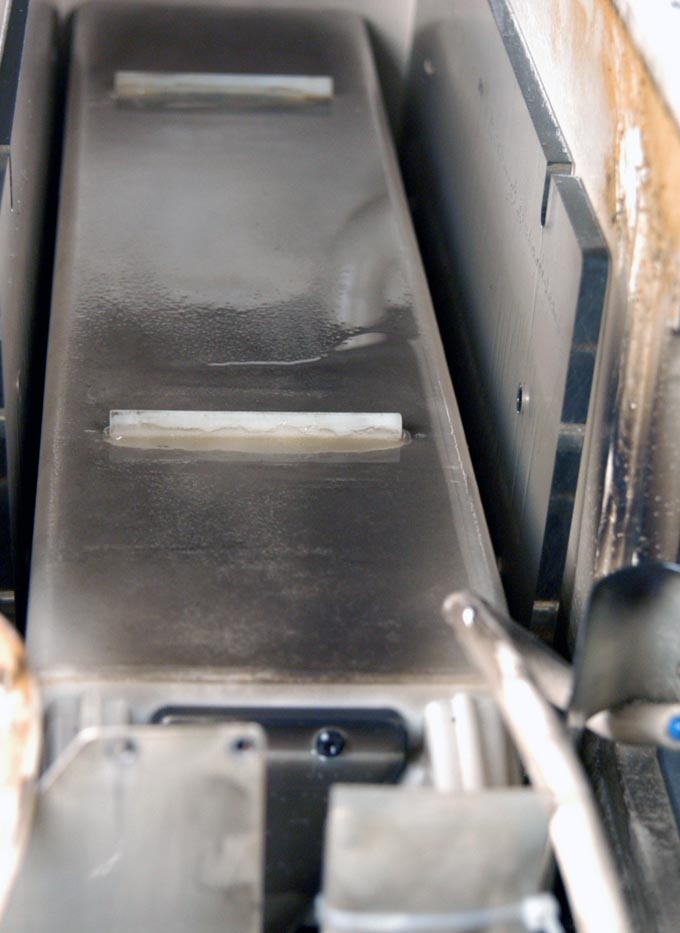
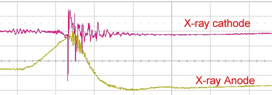
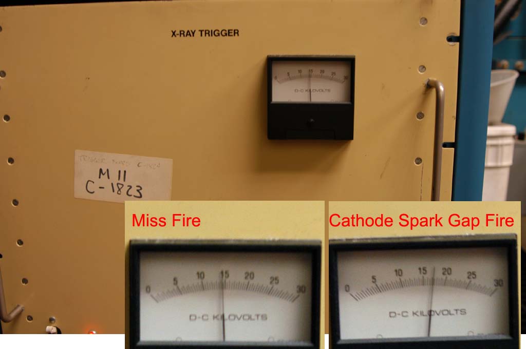 I ran the system this morning, the x-ray cathode pulse still was unstable. Sometimes the cathode spark gap missed fire. The high voltage monitor showed the voltage was 17 kV when the spark gap fired, but it was dropped down to 15 kV after several shots, then spark gap missed fires. Please looked at the picture named voltages.jpg. Mike suggested we should cut the voltage cable input ends, he guessed that damaged cables caused the voltage decrease because of the breakdown. So we cut both cable input and output ends. We really found there were some tracks on the cable surface, please check the pictures named "input ends.jpg" and "output ends.jpg".

Unfortunately, the x-ray cathode spark gap still missed fires e
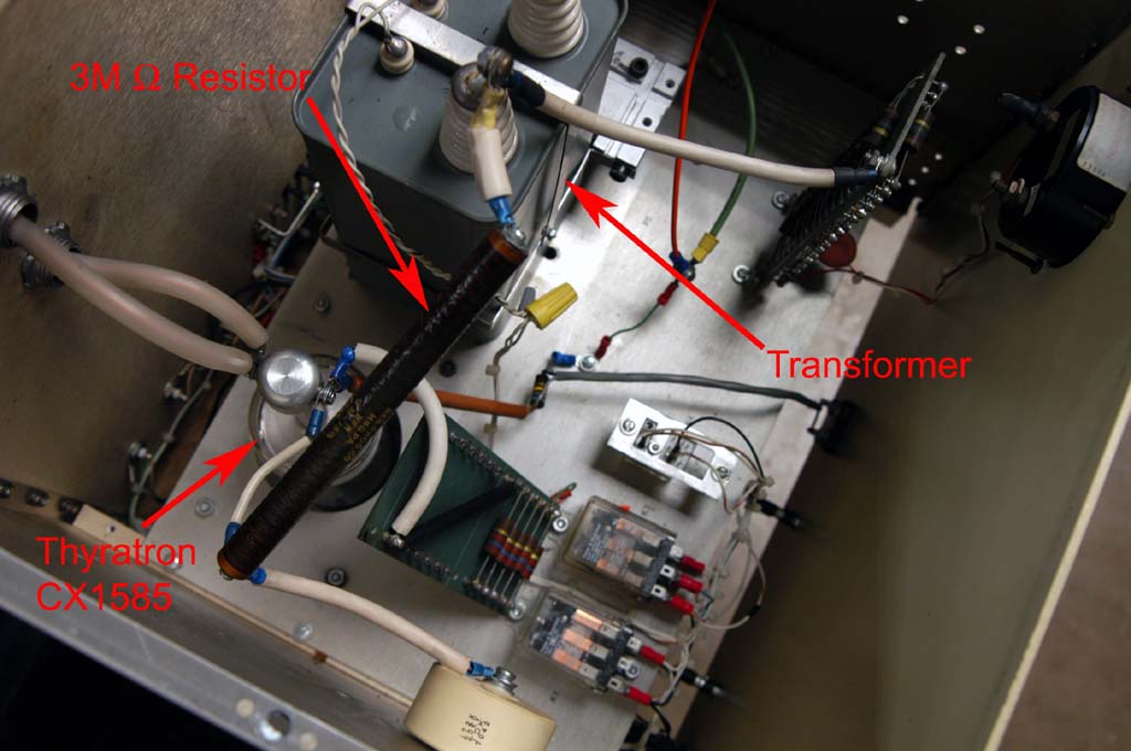 ven I repaired the cable ends. We have not found the main point of the voltage decreasing yet. Mike guessed the 3M Ohm resistor does not work well, he asked me to check it tomorrow. But I think that the transformer may not work properly, since the voltage monitor is mearuing the transformer output. I want to measure the transformer output without connecting the thyratron firstly, make sure the voltage source is all right.
Subscribe to:
Comments (Atom)